PSX-5300 Installation PSX Module Installation and Cable Connection
DOC-001-11001 (Rev. 006)
35 DNX Quick Install & Setup Guide
Connecting N+1 Protection Switch DC Power (-48VDC)
Note: To insure DC power redundancy is maintained, use two DC Power Supply Modules, in
conjunction with power sources from two separate fuse panels or from a fuse panel
with redundant (A and B) fuse positions.
1. Mount the unit above a DNX-11 unit in a rack as specified previously.
2. Shut off -48VDC power to the DC supply leads.
3. Strip the insulation back approximately 5/16 inch (8mm) from the end of each lead.
4. Note the positions of earth, negative and positive on the DC power plug (designations are
on the DC Power Supply Module faceplate).
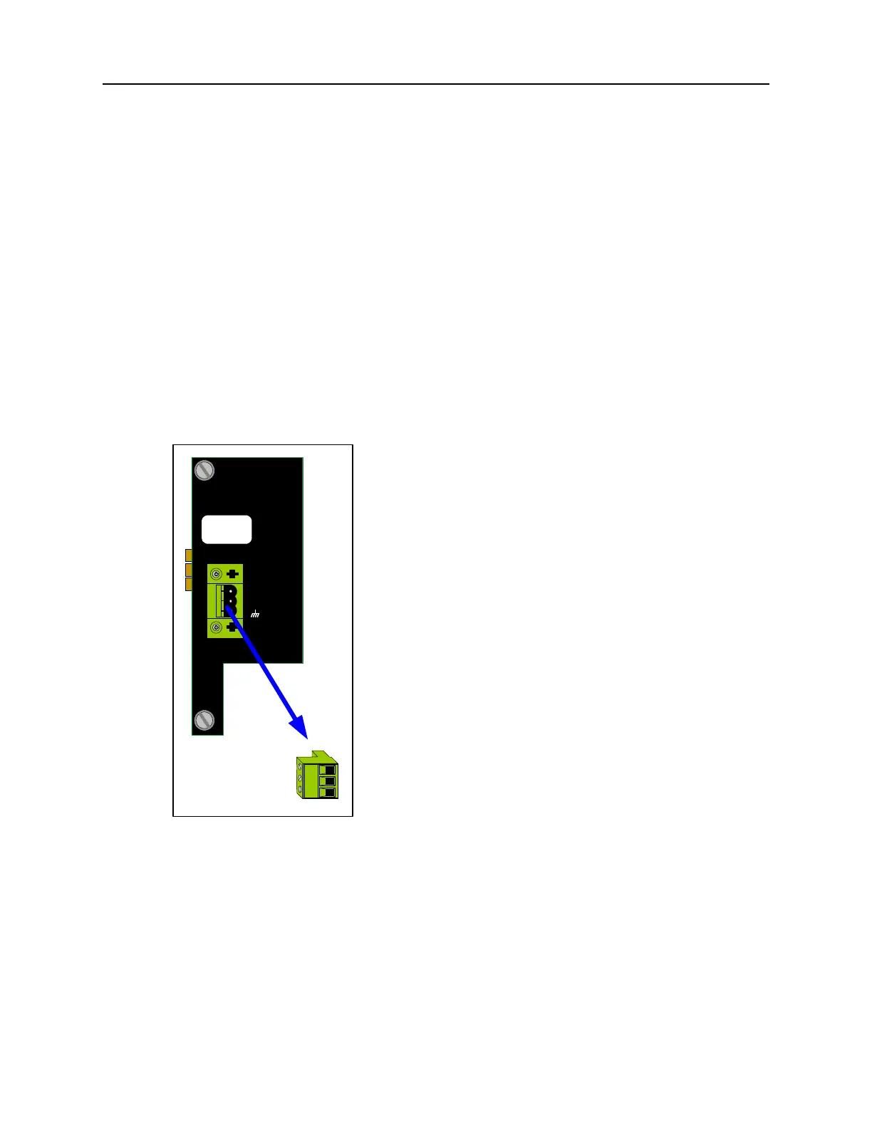
5. Remove the DC power terminal block from the mating receptacle on the DC Power Supply
Module faceplate (see Figure 27).
Figure 27: Remove Power Terminal Block.
6. Insert the “earth” lead into the earth terminal clamp on the power terminal block and tighten
the clamp screw using a small flat screwdriver (see Figure 28).
DC POWER
+
-
WARNING
Remove Power Cable
Before Removing Module
FUSE: F2A - 250VAC