PSX-5300 Installation PSX Module Installation and Cable Connection
DOC-001-11001 (Rev. 006)
34 DNX Quick Install & Setup Guide
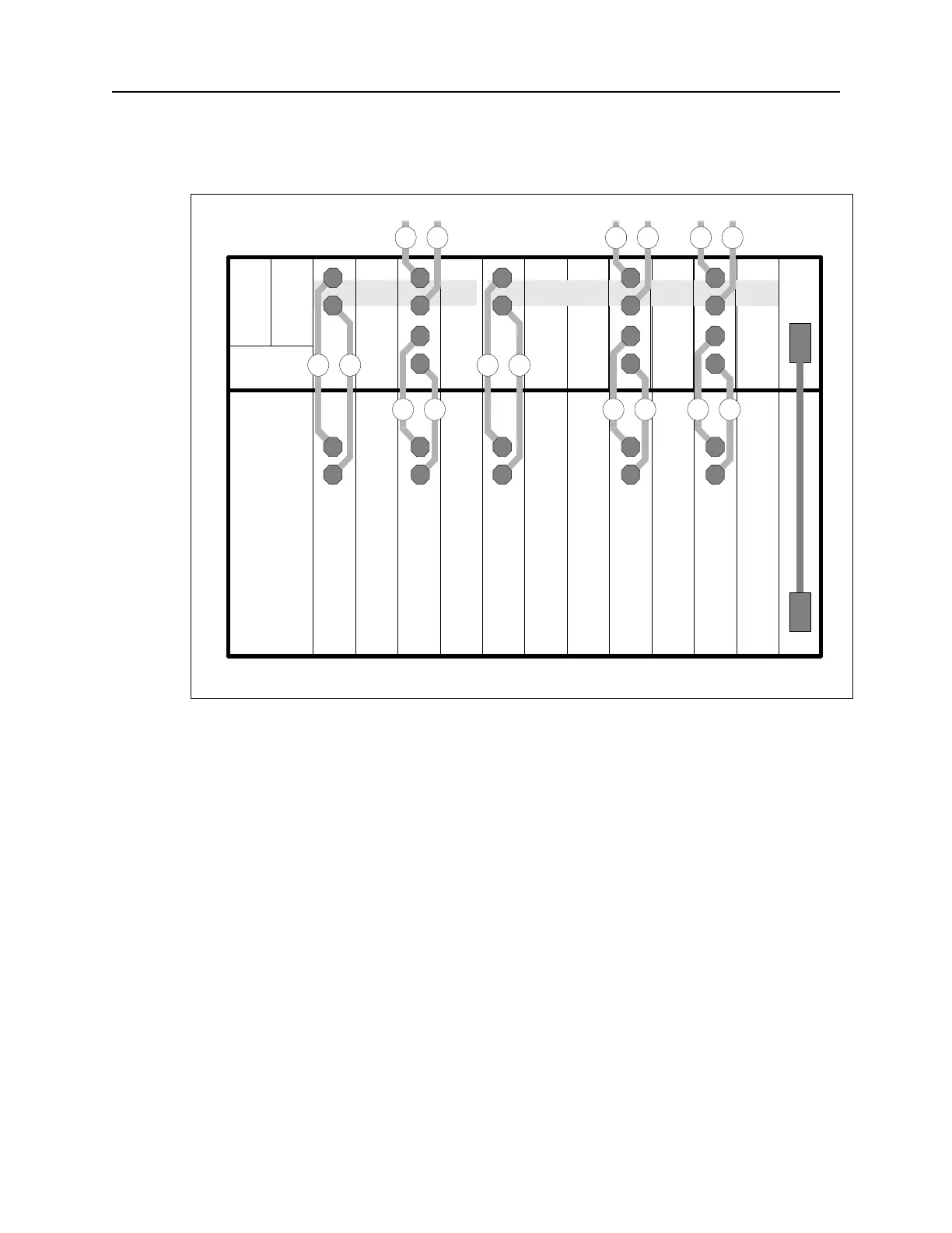
Figure 26: PSX Broadband Cable Installation.
Figure Notes: In Figure 26, slot 9 contains a Broadband Group 1 primary interface module,
and slot 1 contains the Broadband Group 1 backup module. Slots 2 and 4 contain Broadband
Group 2 primary interface modules, and slot 7 contains the Broadband Group 2 backup module.
The numbers on the cables correspond to the steps in the Broadband Connection procedure on
the previous page.
Note: To power up, refer to ““Connecting N+1 Protection Switch DC Power (-48VDC)”” on the
following page.
SM1234567891011POWER
CTL
POWER
N+1 Protection SwitchDNX-11
BB1 BB2
R
T
OUT
T
R
IN
R
T
1 1
2 3
OUT
T
R
R
T
5 4
OUT
T
R
R
T
5 4
R
T
OUT
T
R
IN
R
T
1 1
2 3
R
T
OUT
T
R
IN
R
T
1 1
2 3
 Loading...