PSX-5300 Installation PSX Module Installation and Cable Connection
DOC-001-11001 (Rev. 006)
32 DNX Quick Install & Setup Guide
Narrowband Cable Connections
1. Connect the 50-pin cable from the network to the 50-pin connector that is on the PSX
Narrowband Primary module.
2. Connect the 50-pin cable from the Narrowband Primary module to the corresponding 50-pin
connector that is on the DNX Narrowband (Octal T1/E1) rear interface module.
3. Attach the 50-pin male-to-male cable (part # CBE-048-50501) from the Narrowband
Redundant module to the Standby slot 1 on the DNX-11.
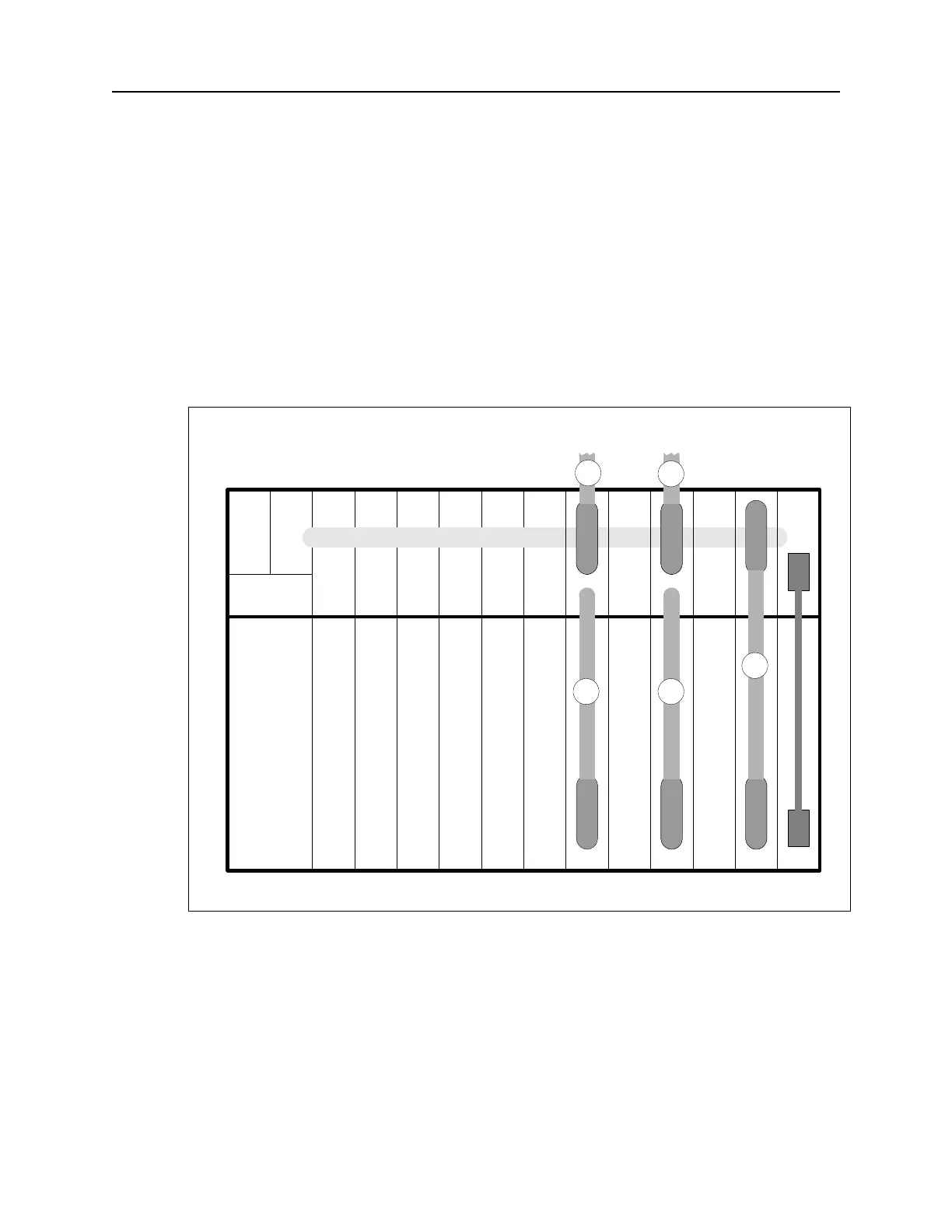
Figure 25 illustrates a PSX connection for Narrowband Redundancy.
Figure 25: PSX Narrowband Cable Installation.
Figure Notes: In Figure 25, slots 3 and 5 contain Narrowband primary interface modules, and
slot 1 contains the Narrowband Group backup module. The numbers on the cables correspond
to the steps in the Narrowband Connection procedure above.
Note: To power up, refer to ““Connecting N+1 Protection Switch DC Power (-48VDC)”” on
page 35.
SM1234567891011POWER
CTL
POWER
N+1 Protection SwitchDNX-11
Links 1-8Links 9-16
NARROWBAND BUS (10+1)
1
1
2 2
3