PSX-5300 Installation PSX Module Installation and Cable Connection
DOC-001-11001 (Rev. 006)
36 DNX Quick Install & Setup Guide
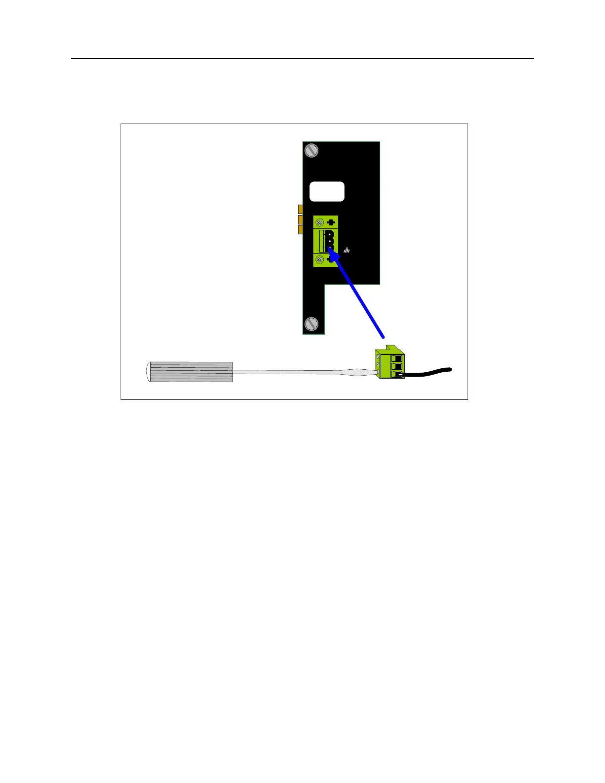
Figure 28: Connecting DC Power Leads.
7. Insert the “-48 volt supply” wire into the negative terminal clamp and tighten the clamp
screw.
8. Insert the “return” wire into the positive terminal clamp and tighten the clamp screw.
9. Insert the power terminal block into the mating receptacle on the rear panel (see Figure 28).
10. Repeat steps 2-9 if the PSX-5300 has a second (redundant) DC Power Supply Module
installed.
11. To minimize disturbance to the wires through casual contact, secure the power cables to
the rack frame using multiple cable ties. The first tie should be located within 6 inches of
the terminal block.
12. Power up both the DNX-11 and N+1 Protection Switch. The LED on the PSX Controller
Module will flash as the unit powers up, loads software, and runs a self-test. This will take a
few minutes, depending upon how many modules have been configured.
13. Once the system is powered up, you should see a flashing
Green READY LED on the N+1
Protection Switch Controller module; a solid
Green READY LED on the Online SMC II; and
a flashing
Green READY LED on the Standby SMC II.
Note: Ignore any alarms at this point.
To verify the protection switch installation, refer to “Verifying Protection Switch Installation” on
page 44.
DC POWER
+
-
WARNING
Remove Power Cable
Before Removing Module
FUSE: F2A - 250VAC