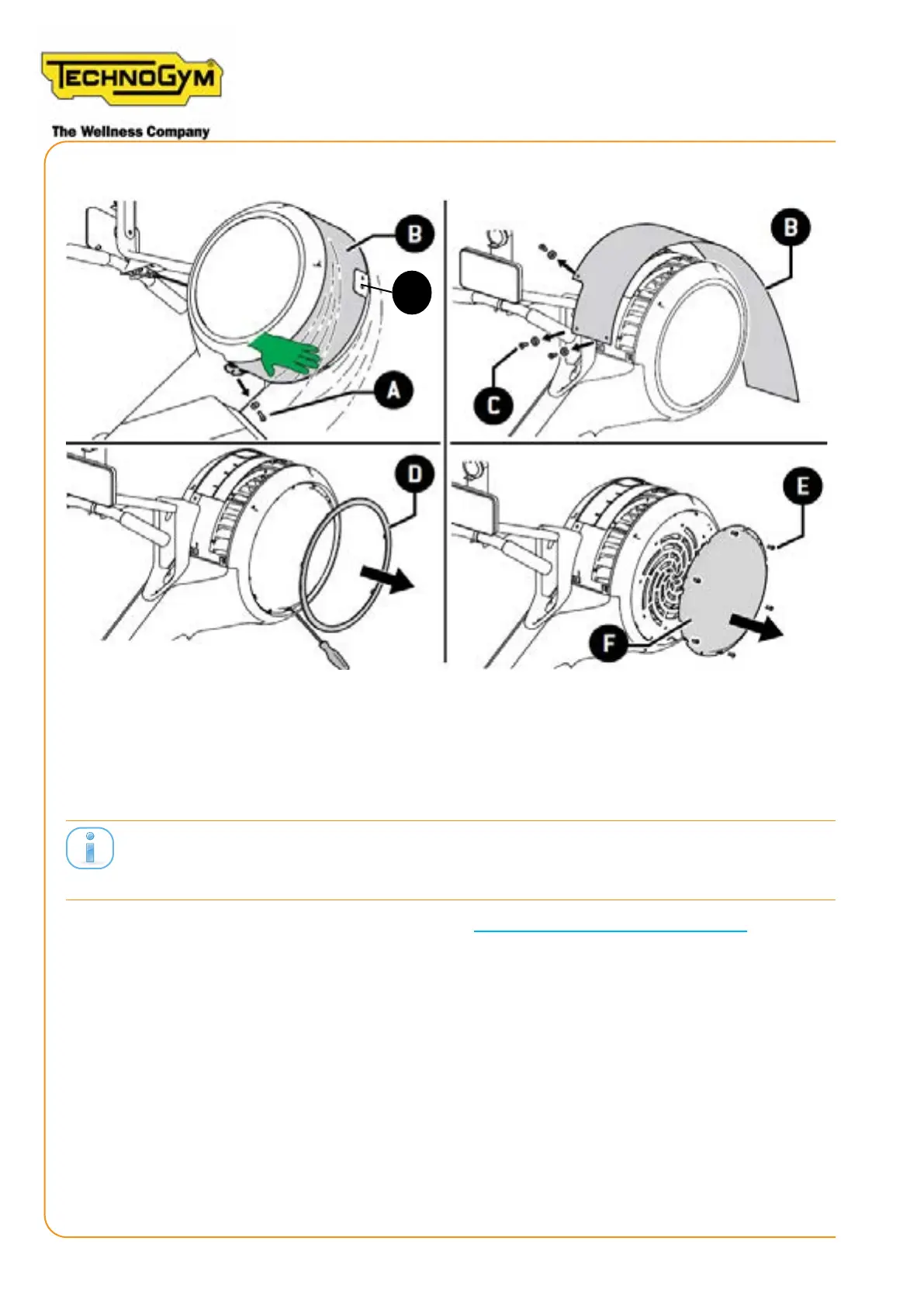
to rst tighten the screws (C), and only at the end the screw (A).
Figure 40
7.3 DISASSEMBLING THE LEFT SPIRAL GUARD
Thedisassemblyofthefollowingguardsprovidesaccesstothegenerator,thelowkitboardandca-
bles.
1. Follow the procedure described at the paragraph “7.1 disassembling the left guard”.
2. Unscrew the 4 screws of the left spiral guard (TOOL: 2.5mm hex wrench). Then, remove the left
yellow ring (D) to unscrew the 4 hidden screws (TOOL: Medium Phillips screwdriver).
G
SKILLROW:
Technical Service Guide - Rev. 1.1
Page 74
e-mail: support@technogym.com