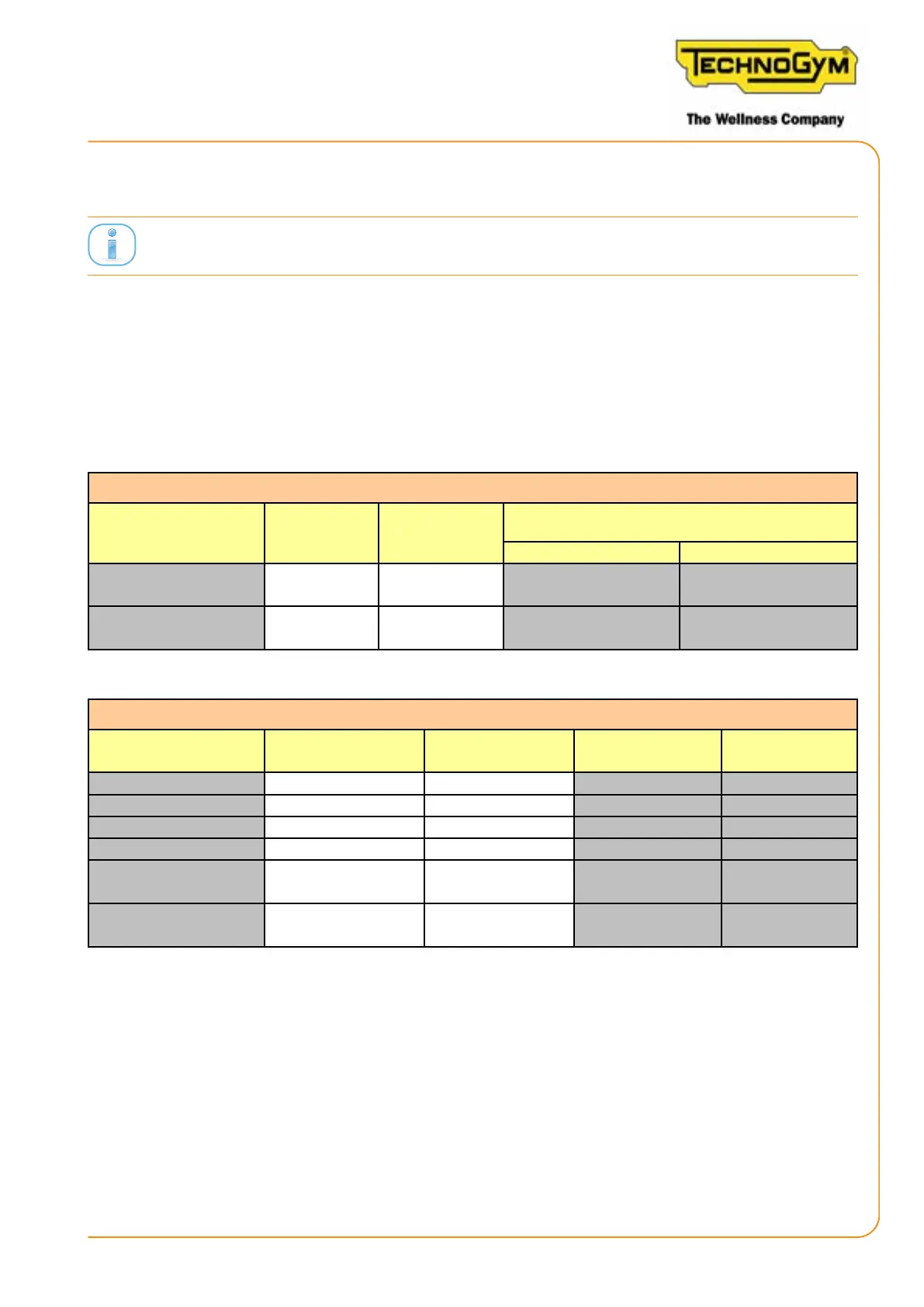
2.8 WIRING DIAGRAM
LOW KIT BOARD
CPU
MAINBOARD
SENSOR ANGLE
BOARD
0WCU0942xx
TOUCH BOARD
DISPLAY
CONSOLE U.I
0WCU0941xx
GENERATOR
0WCU0944xx
NFC BOARD
0WCU0943xx
0WCU0972xx
0WCU0971xx
0WCU0973xx
(A)
(B)
(C)
JACK
24V
J10 J7 J1 J2
FLY
CONNECTION
FLY
CONNECTION
FLY
CONNECTION
(SCWR)
0WCU0959xx
BATTERY
12V
Figure 5
2.9 CABLES
The colour of the cables may change: in particular, refer to the Pin Out.
The following three cables are internal to the Console U.I:
0WCU0971xx = Cable UI/NFC
0WCU0972xx= Cable UI/ knob sensor
0WCU0973xx = Cable UI / RPM - Low Kit Board
0WCU0959xx: Low Kit Board - Baery cable
Low Kit Board Signal Colour
Baery
Positive Negative
1 Baery (+)
Red (alterna-
tive brown)
Faston
2 Baery (-)
Black (alterna-
tive blue)
Faston
Table 7
0WCU0944xx: Low Kit Board / Generator + Jack Cable
Low Kit Board Signal Colour Generator
Jack Power
Supply
1 AC1 (DC-) Green 1
2 AC2 (RPM) Brown 2
3 AC3 (DC+) White 3
- - -
5
Power Supply
(+Vdc)
Red 1
6
Power Supply
(GND-)
Black 2
Table 8
SKILLROW:
Technical Service Guide - Rev. 1.1
Page 21e-mail: support@technogym.com