10 TEGAM WAY • GENEVA, OHIO 44041 • 440-466-6100 • FAX 440-466-6110 • sales@tegam.com
5-6
PROGRAMMING AND INTERFACING
There are a total of 15 pins in connector, J8. The connector contains relay and TTL I/O pins used for
interfacing to PLCs and other control devices. The TTL outputs, 74LS03, are compatible with most TTL
logic type devices. Their states are updated after each reading cycle.
The output relay contacts change their state as a function of the comparator/ binning outputs. There
are normally open and normally closed contacts available for each of the comparator outputs. Their
states are updated after each reading cycle. The contacts are rated at 125 VAC @ 500 mA or 30 VDC
@ 1 A.
Below is a list of these pins and a brief description of what their functions are.
1. Comparator High Output – Contact - Common
2. Comparator Hi Output – Contact - Normally Closed
3. Comparator Hi Output – Contact - Normally Open
4. Digital Common
5. Comparator Low Output – Contact - Common.
6. Comparator Low Output – Contact - Normally Closed
7. Comparator Lo Output – Contact - Normally Open
8. Digital Common
9. Comparator Go Output – Contact - Common.
10. Comparator Go Output – Contact - Normally Closed
11. Comparator Go Output – Contact - Normally Open
12. Digital Common
13. Comparator High LS Open Collector, TTL Output, Pull Up Resistor Required
14. Comparator Low LS Open Collector, TTL Output, Pull Up Resistor Required
15. Comparator Go LS Open Collector, TTL Output, Pull Up Resistor Required
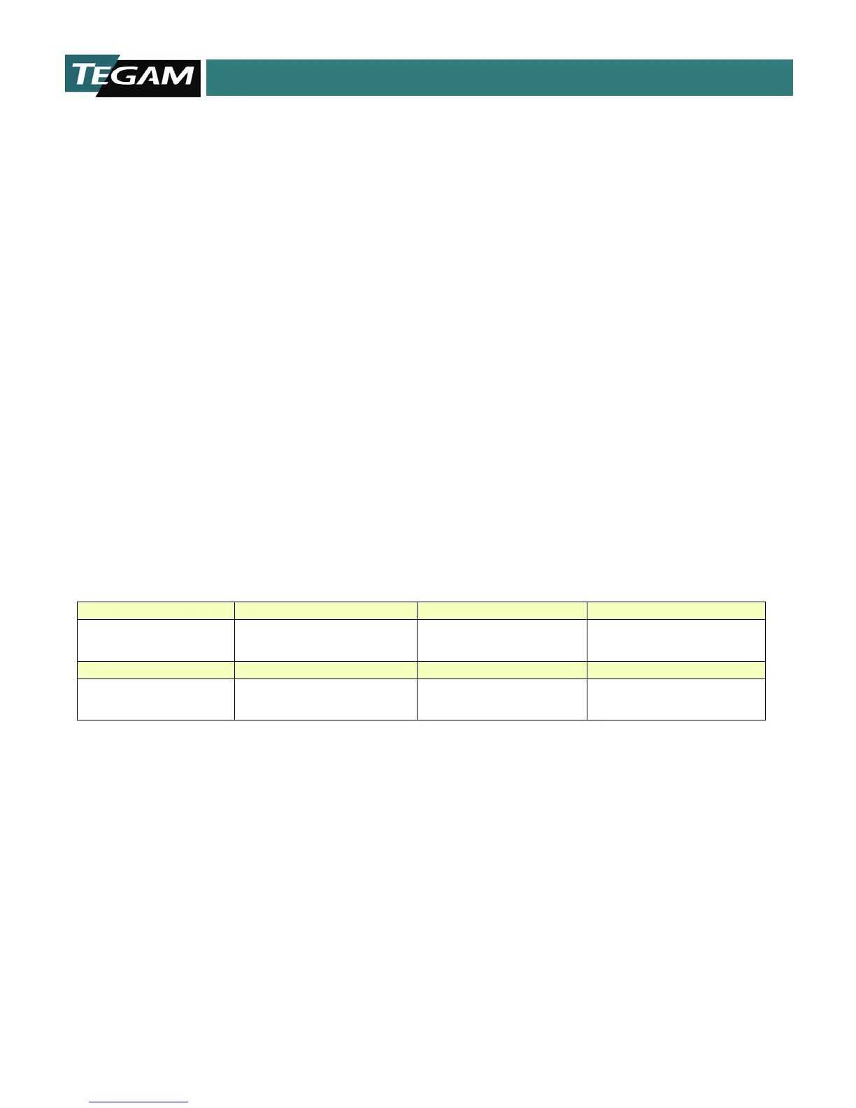
GO
Open Collector TTL outputs
Requires pull up resistor up
to 28 VDC pull up voltage.
LOGIC HIGH=
V
(pull-up)
- .8 VDC
< 0.5 VDC
COMPARATOR RELAY
OUTPUTS
Normally Open and Normally
closed relay outputs for
30 VDC @ 1 A 125 VAC @ 0.5 A
Table 5.2: Connector, J8 Electrical Requirements