Calibration
6–30
1502C MTDR Service Manual
(+)
GND
R8043
R8042
R8041
R8040
R9032
R9031
C9035
C9034
C9033
R9030
C9032
U9030
C9031
C9030
C9025
R9027
Q9021
C9024
R9026
R9025
R9024
C9023
R9023
C8022C8024
R8028
R8027
R8026
CR8029
R8025C7022
R7024
R7025
R7026
R7027
Q7021
R7028
C7023
R7030
R7031
R7032
R7033
C2030
Q7030
R7034
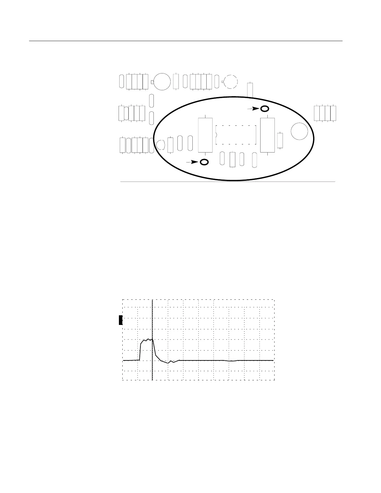
Figure 6–48: Main Board Probe Points
Test points in this check are located on the Main Board.
1. Move the positive (+) probe to the ground side of C9035 (the side away from
the edge of the board).
2. Verify that the voltage is –11.8 to –12.2 VDC.
3. Verify that the LCD shows the following display:
O
F
F
O
F
F
O
F
F
O
N
ac 0.000 ft
Figure 6–49: Waveform on Display
You might have to adjust R1018 (Contrast Adjust) on the Front Panel Board to get
a clear display (see LCD Check and Adjustments in this section).
–12 VDC
Artisan Technology Group - Quality Instrumentation ... Guaranteed | (888) 88-SOURCE | www.artisantg.com