Calibration
1502C MTDR Service Manual
6–31
1. Turn the POWER off.
2. Remove the AC plug from the rear panel of the instrument.
3. If a battery is present, disconnect the wire from the battery to the Power Supply
board.
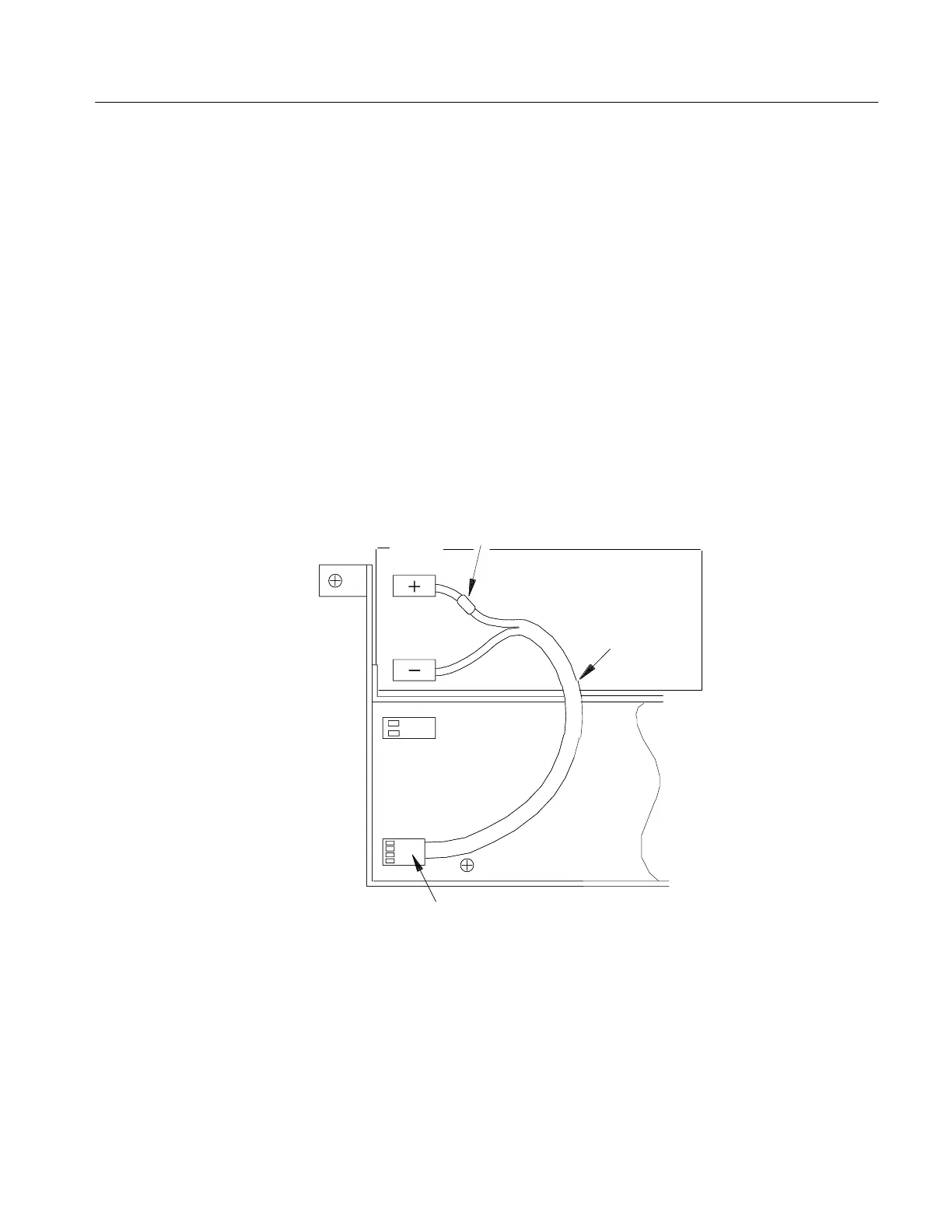
4. Connect an external 12 VDC power supply into the battery connector (see
Figure 6–50). Pins 1 and 4 are ground. Pins 2 and 3 are positive (supply)
terminals.
5. Adjust the external 12 VDC supply for +11.5 VDC output at the terminals of
the battery input.
6. Connect a DC ammeter in series with the positive (+) side of the 12 VDC supply.
7. Turn the power on. The current measurement must not exceed 350 mA.
Battery
Red
Orange
&
Yellow
&
Brown
Fuse
Battery Connector J2010
Wire
Power Supply Board
Figure 6–50: Battery Connections to Power Supply Board
8. Connect the positive (+) probe of the voltmeter to the front side of CR2012 on
the Power Supply Board (this is the large diode next to J2010. The positive
probe should be on the non-banded end of the diode).
9. Connect the negative probe to ground.
DC Power Check
Artisan Technology Group - Quality Instrumentation ... Guaranteed | (888) 88-SOURCE | www.artisantg.com