Maintenance
1502C MTDR Service Manual
7–11
CAUTION. Do not further disassemble the Display Module. Elastomeric splices are
used between the circuit boards and they require special alignment fixtures. Parts
replacement requires special surface-mount technology.
The instrument will power up displaying DIST/DIV measurements as meters
(m/div) or feet (ft/div). Although either measurement mode may be chosen from the
Setup Menu, the default can easily be changed to cause the preferred mode to come
up automatically at power up.
1. Remove the instrument from the case.
2. Remove the bottom EMI shield.
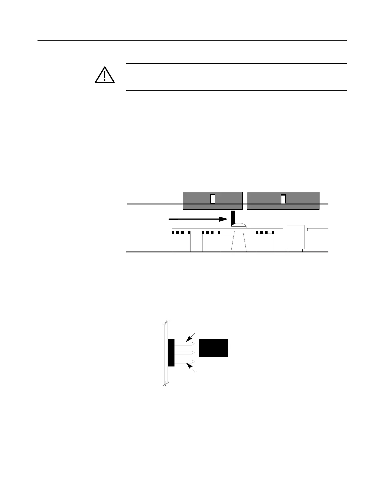
Jumper
Front Panel
Board
Main Board
Ribbon Cable Connectors
Figure 7–8: Location of Default Jumper on Front Panel Board
3. From the bottom side of the instrument, peer into the space between the Main
Board and the Front Panel Board. The default jumper is located behind the
screw that holds the Front Panel Assembly to the front-panel mounting stud.
Standard
Metric
Top of Instrument
Bottom of Instrument
Front
Panel
Board
Jumper
Figure 7–9: Default Jumper Positions
4. Using a needle-nose plier, slip the jumper off the pins and move it to the desired
default position (top for meters, bottom for feet).
Changing the Default to
Metric
Artisan Technology Group - Quality Instrumentation ... Guaranteed | (888) 88-SOURCE | www.artisantg.com