Maintenance
7–10
1502C MTDR Service Manual
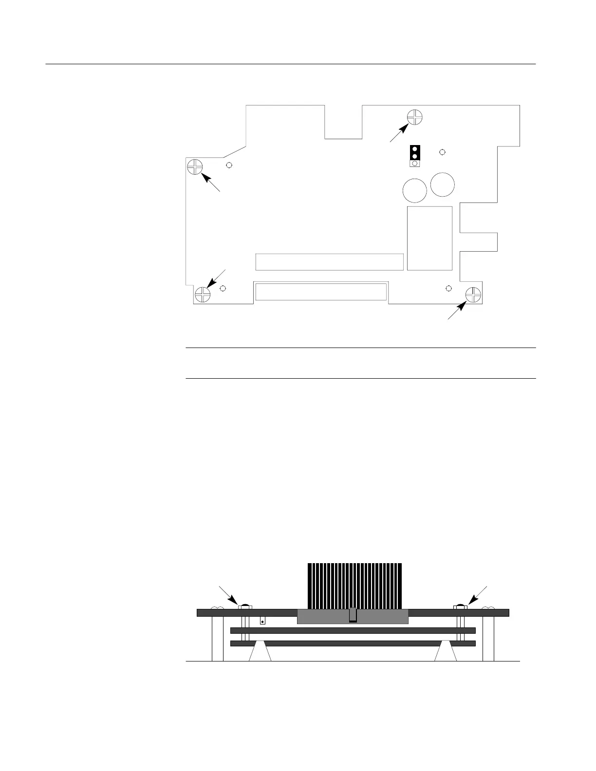
Figure 7–6: Display Module/Front Panel Board Screw Locations
NOTE. When re-assembling, push the rubber boot down on the switch shaft so that
the switch button can easily be replaced.
5. Remove the four screws holding the Display Module/Front Panel Board to the
front panel (see Figure 7–6).
6. Carefully lift the Display Module/Front Panel Board from the front panel.
1. Remove the four hex nuts (two are shown in Figure 7–7) that hold the Display
Module to the Front Panel Board.
2. Disconnect the ribbon cable from the boards.
3. Carefully separate the Display Module from the Front Panel Board.
Figure 7–7: Display Module/Front Panel Board Showing Hex Nuts
Removing the Front Panel
Board from the Display
Module
Artisan Technology Group - Quality Instrumentation ... Guaranteed | (888) 88-SOURCE | www.artisantg.com