Operator Performance Checks
2–2
1502C MTDR Service Manual
Set the 1502C front-panel controls:
NOISE FILTER 1 avg
VERT SCALE default
DIST/DIV 1 ft/div (0.25 m)
Vp .66
If the instrument fails this check, it must be repaired before any distance
measurements can be made with it.
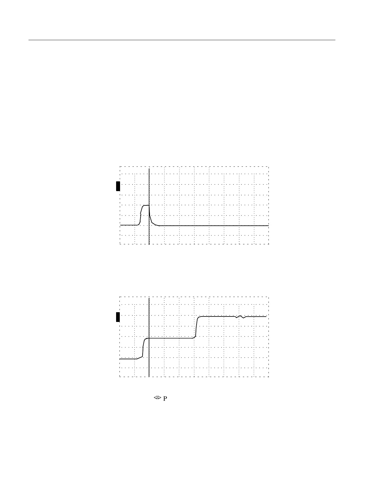
1. Turn the 1502C power on. The display should look very similar to Figure B–1.
O
F
F
O
F
F
O
F
F
O
N
ac 0.000 ft
Figure 2–1: Start-up Measurement Display
2. Connect the 3-foot precision cable to the front-panel CABLE connector. The
display should now look like Figure B–2.
O
N
ac 0.000 ft
O
F
F
O
F
F
O
F
F
Figure 2–2: Measurement Display with 3-foot Cable
3. Using the
n
o
POSITION control, measure the distance to the rising edge of the
waveform at the open end of the cable. The distance shown on the display
distance window (upper right corner of the LCD) should be from 2.87 to 3.13
feet (0.875 to 0.954 m).
Set Up
1. Horizontal Scale
(Timebase) Check
Artisan Technology Group - Quality Instrumentation ... Guaranteed | (888) 88-SOURCE | www.artisantg.com