Circuit Descriptions
5–18
1502C MTDR Service Manual
16 BIT
400 ns
3 bit
prgm
delay
14 BITDAC
OUTPUT
PROGRAMMED DELAY
(a)
(b)
(c)
(d)
(e)
(f)
(g)
PRT
COUNTER
DELAY
COUNTER
DRIVER
STOBE
FINE
DELAY
RAMP
TRIGGER
RAMP
GENERATOR
SAMPLER
STROBE
COURSE
COUNTER
[EXPANDED]
[EXPANDED]
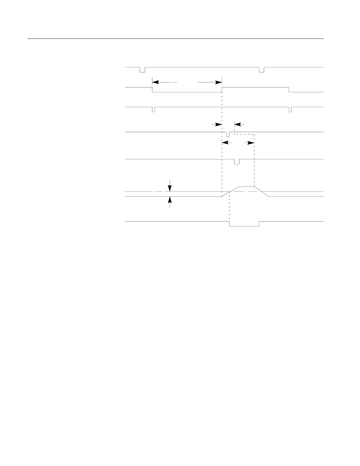
Figure 5–10: Combined Effects of Time Delay
At the end of the coarse delay, the rising edge of this signal enables the fine delay
(d), which produces a single ramp trigger pulse after the programmed delay. This
pulse is shown expanded in waveform (e). The ramp generator waveform (f), also
shown expanded, has a linear voltage ramp beginning on the falling edge of the
trigger. This voltage is compared to the voltage from the timebase DAC, such that
when the ramp exceeds the DAC voltage, the sampler strobe (g) falls. This falling
edge is used as the sampler strobe for video sampling.
At the beginning of each sweep, the zero distance reference is calibrated to the
front-panel connector and the length of the analog ramp to 50 ns.
Zero distance reference is calibrated by setting the digital and analog timebase for
zero delay. Then the processor adjusts the driver delay so as to sample at the 10%
point of the pulse. The ramp is calibrated by removing 50 ns of delay (one 50-ns
clock cycle) from the sample trigger and then reinserting it with the analog delay.
The processor adjusts the reference for the timebase DAC so as to sample at the
previous level. This matches the analog delay to the 50-ns period of the clock.
Artisan Technology Group - Quality Instrumentation ... Guaranteed | (888) 88-SOURCE | www.artisantg.com