Circuit Descriptions
1502C MTDR Service Manual
5–31
There is one row driver, located on the Row Driver/Controller Board. There are eight
column drivers, located on the Column Driver Board. The row and column drivers
receive control, timing, and data signals from the controller and translate them to
properly timed voltages that are placed on the pixel matrix. The voltages are placed
on the matrix by the flex cable for the rows and by the elastomers for the columns.
ROW 64 - ROW 128 ROW 1 - ROW 65
GND
N.C.
LATCH
64 - BIT SHIFT REGISTER
64 - BIT LATCH
64 - BIT LEVEL SHIFTER
LP
ST
Vccd
V5
V2
+5
FR
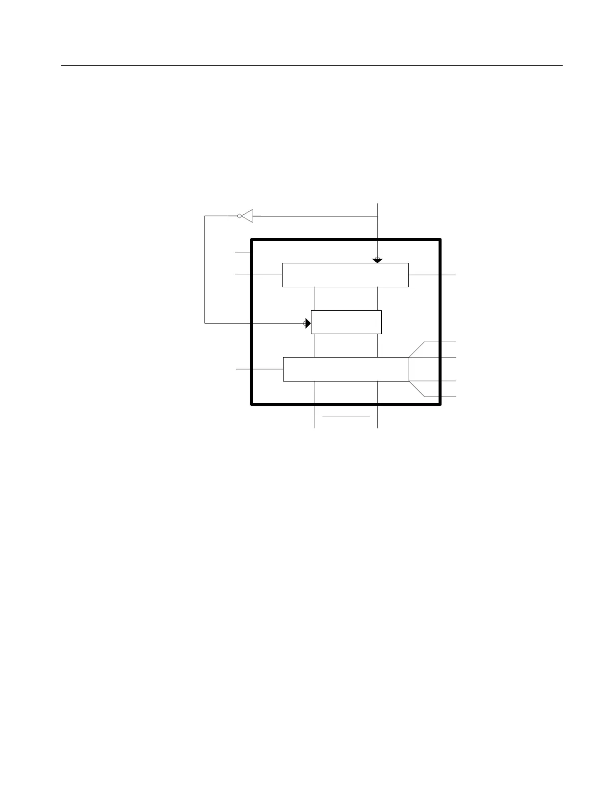
Figure 5–16: Row Driver Block Diagram
The function of the row driver is to sequentially address each of the rows of the
display. The on or off state of the pixels on the addressed row is then determined by
the voltages on the columns. The row driver addresses each line, one after another,
completing the scanning at the refresh rate of 125 Hz.
The column driver is similar to the row driver except bit pattern data is level-shifted
rather than the start pulse. The column drivers provide select and non-select voltages
to the column electrodes according to the bit pattern data. The presence of select
or non-select voltages on the columns, in conjunction with the currently selected
row pair determine which pixels are on or off on that row pair. The column drivers
regulate the select and non-select voltages as the row drivers select rows. The result
is a bit pattern displayed on the screen that represents a waveform.
Row and Column Drivers
Artisan Technology Group - Quality Instrumentation ... Guaranteed | (888) 88-SOURCE | www.artisantg.com