Circuit Descriptions
5–32
1502C MTDR Service Manual
Gnd
Vlcd
V4
V3
+5
Eclk
Ein
Eout
Xscl
D3
D2
D1
D0
Lp
Fr
Column X 64
Column X
Seg 63
64 - Bit Level Shifter
64 - Bit Latch
16 position
4-bit wide
shift register
DQ
Q
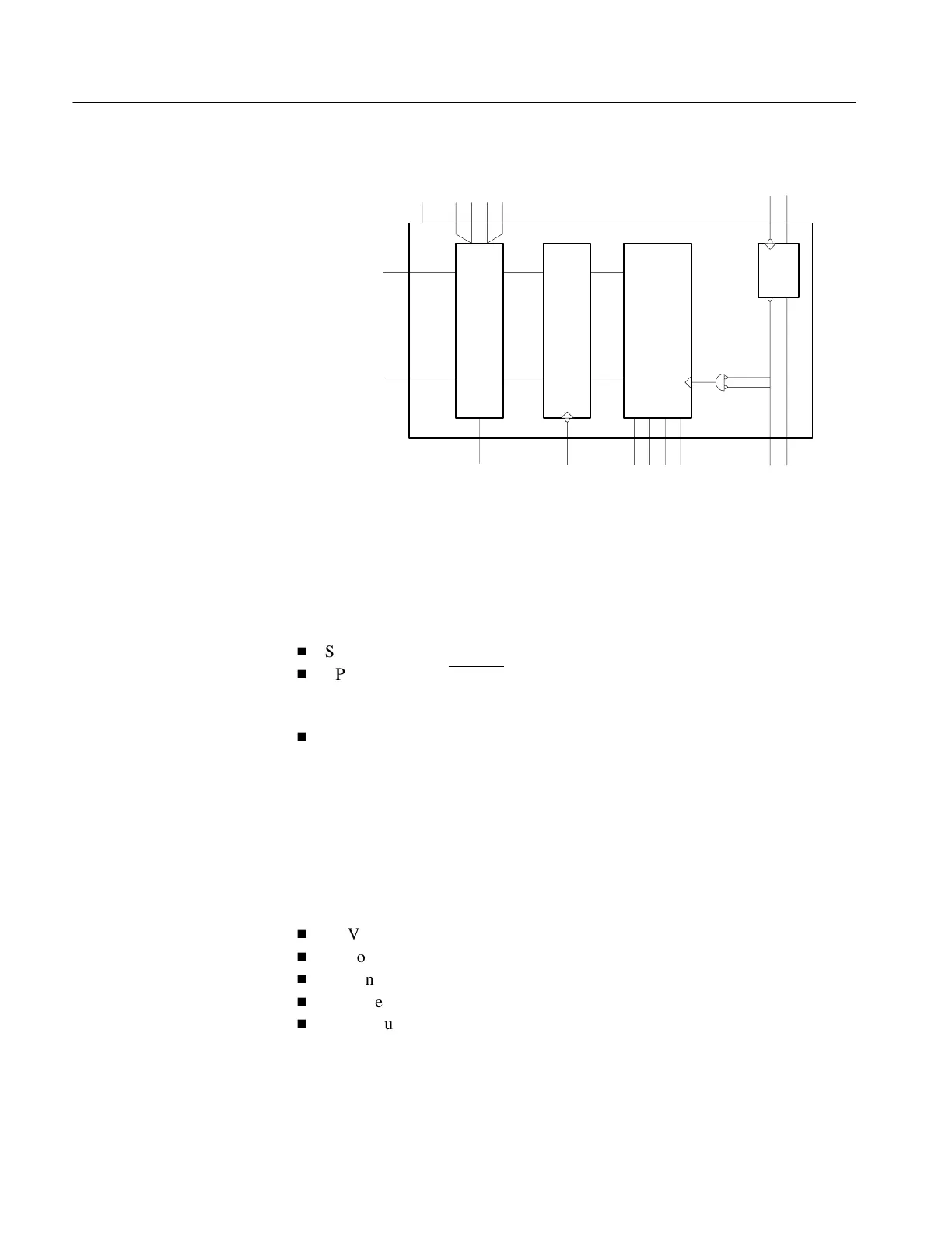
Figure 5–17: Column Driver Block Diagram
The row driver is an 80-pin flat pack located on the Row Driver/Controller Board.
It is composed of a 64-bit shift register, U2020, a 64-bit latch, and a 64-bit level
shifter. The row driver has the following relevant inputs:
H
ST <start pulse>: Input to the shift register <Din on SED 1190>
H
LP <latch pulse = LATCH
>: Falling-edge triggered, this shifts data in the shift
register and latches contents of the shift register into the latch <Y S
CL
on
SED 1190>
H
FR <frame signal>: Defines the select and non-select voltages.
The relevant outputs:
Row 1 through 64 are paralleled outputs driving both sides of the display. One set
of outputs drive rows 1 through 64 and the other set drive rows 65 through 128 on
the LCD.
Supply Voltages include the following:
H
+5 VDC supply voltage for logic and select drive voltage
H
V
2
non-select drive voltage
H
V
5
non-select drive voltage
H
V
LCD
select voltage
H
GND return for +5 VDC.
Row Driver
Artisan Technology Group - Quality Instrumentation ... Guaranteed | (888) 88-SOURCE | www.artisantg.com