Circuit Descriptions
1502C MTDR Service Manual
5–33
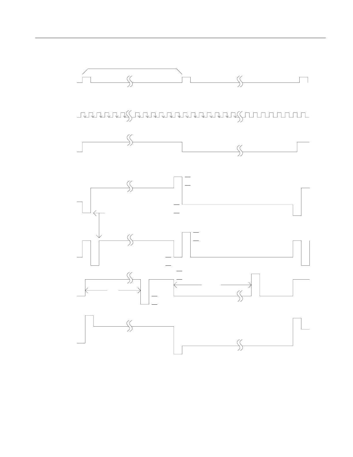
1 Frame = 8 ms
63 64 1 2 3 63 64
+5
V2
Scanning select pulse
V5
V
LDC
+5
V2
V5
V
LDC
V5
V
LDC
+5
V2
LP
X–LP
Figure 5–18: Row Timing Diagram
To perform its function, the row driver receives a start pulse at the beginning of a
frame. LP shifts this start pulse into the shift register. The contents are then
transferred to the latch. The level shifter shifts the logical 1s and 0s in the latch into
select and non-select voltages according to FR (see table at top of next page).
Artisan Technology Group - Quality Instrumentation ... Guaranteed | (888) 88-SOURCE | www.artisantg.com