Circuit Descriptions
5–34
1502C MTDR Service Manual
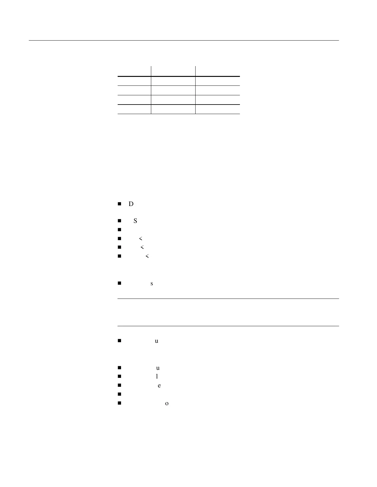
FR Bit X in Latch Row X Output
0 0 V
5
non-select
0 1 +5 VDC select
1 0 V
2
non-select
1 1 V
LCD
select
ST, LP, and FR are sent by the controller in such a way that a scanning select voltage
is applied sequentially to the rows, with the polarity of the select voltage alternating
with FR, every frame. The alteration is required to place an AC voltage on the pixels.
A column driver is composed of several blocks: 16-position, 4-bit wide shift
register; 64-bit latch; 64-bit level shifter; and an enable flip-flop.
A column driver has the following relevant inputs:
H
D3–D0 <data MSB to data LSB>: Bit pattern data for data formatted and sent
by the controller
H
XSCL <column (X) shift clock>: Shifts D3–D0 in parallel groups of four bits
H
LP <latch pulse>: Latches data in shift register into 64-bit latch
H
FR <frame signal>: Defines select and non-select voltages
H
E
IN
<enable in>: Input to the enable flip-flop
H
E
CLK
<enable clock>: Clocks E
IN
into the enable flip-flop.
The relevant outputs:
H
Columns 1 to 64: These are the 64 outputs from the level shifter.
NOTE. The manufacturer’s pinout of the outputs are numbered in order of shift (seg
63 – seg 0). The nomenclature herein refers to the outputs in column order.
Therefore, seg 63 corresponds to Column 1 and seg 0 corresponds to Column 64.
H
EOUT: Output from the enable flip-flop.
Supply Voltages include the following:
H
+5 VDC supply voltage for logic and select drive voltage
H
V
3
non-select voltage
H
V
4
non-select voltage
H
V
LCD
select voltage
H
GND return for +5 VDC
Column Driver
Artisan Technology Group - Quality Instrumentation ... Guaranteed | (888) 88-SOURCE | www.artisantg.com