Circuit Descriptions
1502C MTDR Service Manual
5–35
One Line
Extra
1 116
64
64-LP
(Non Select Bits)
Vlcd (Select Bits)
One Frame
+5V (Select Bits)
V
4
(Non Select Bits)
1
11116 16
16
V
3
First Column
Driver Pair
Enable
Second Column
Driver Pair
Enable
Third Column
Driver Pair
Enable
Forth Column
Driver Pair
Enable
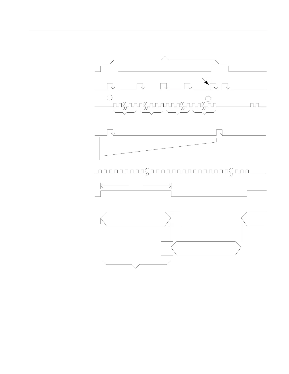
Figure 5–19: Column Timing Diagram
To perform its function, the column driver shift registers are filled with data by
receiving data, XSCL, E
CLK
, and E
IN
from the controller. LP then latches the
contents of the shift registers into the latches. The level shifter translates the logical
1s and 0s in the latch into select and non-select voltages according to FR (see table,
next page).
Artisan Technology Group - Quality Instrumentation ... Guaranteed | (888) 88-SOURCE | www.artisantg.com