Theory of Operation—2230 Service
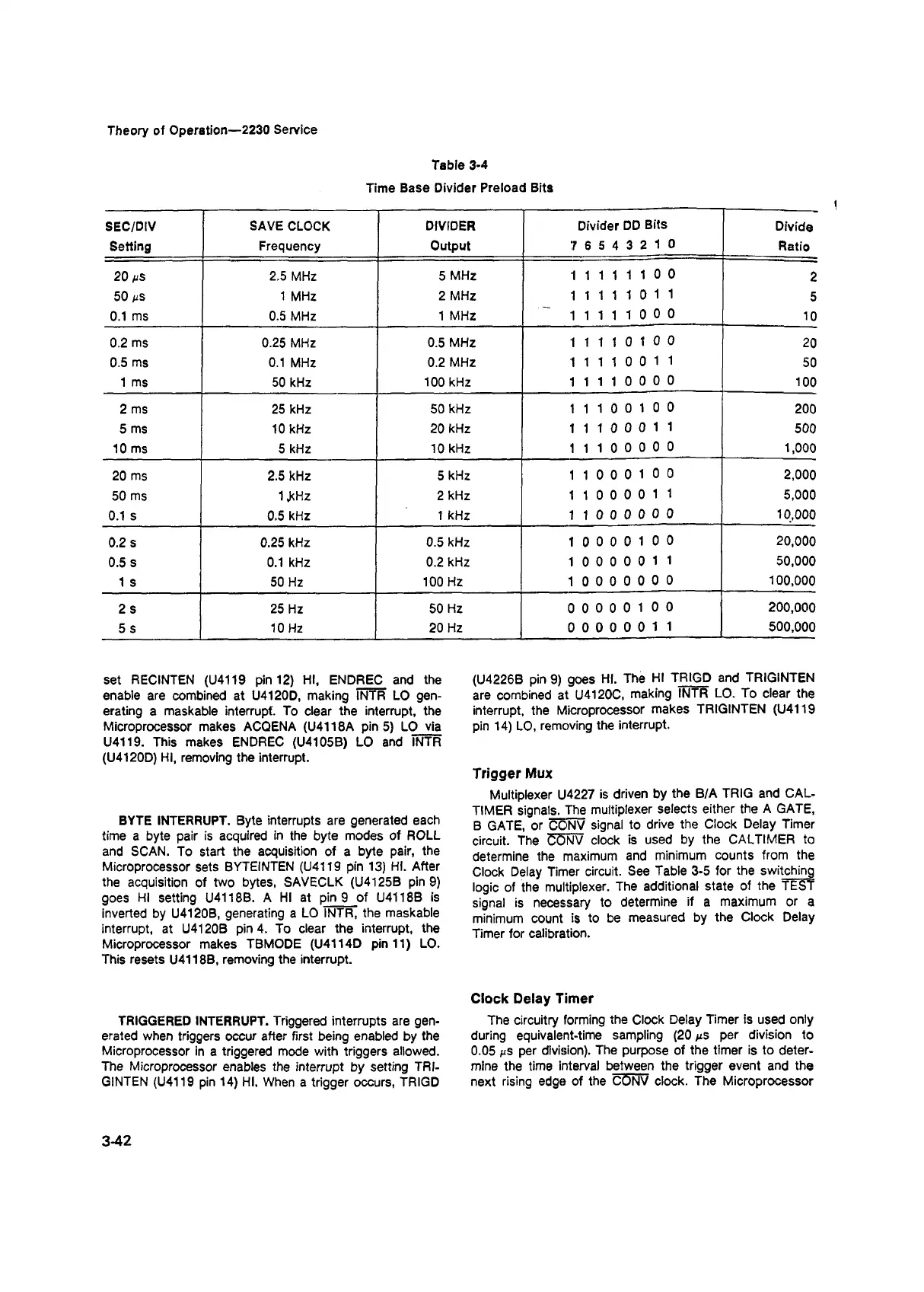
Table 3-4
Time Base Divider Preload Bits
SEC/DIV
SAVE CLOCK DIVIDER
Divider DD Bits
Divide
Setting
Frequency Output
7 6 5 4 3 2 1 0
Ratio
20 ms
2.5 MHz 5 MHz
1 1 1 1 1 1 0 0
2
50 ms 1 MHz
2 MHz
1 1 1 1 1 0 11
5
0.1 ms
0.5 MHz
1 MHz
1 1 1 1 1 0 0 0
10
0.2 ms
0.25 MHz
0.5 MHz
1 1 1 1 0 1 0 0
20
0.5 ms 0.1 MHz 0.2 MHz
1 1 1 1 0 0 11
50
1 ms 50 kHz
100 kHz
1 1 1 1 0 0 0 0
100
2 ms 25 kHz
50 kHz
1 1 1 0 0 1 0 0
200
5 ms 10 kHz 20 kHz
1 1 1 0 0 0 1 1
500
10 ms 5 kHz 10 kHz
1 1 1 0 0 0 0 0
1,000
20 ms 2.5 kHz
5 kHz
1 1 0 0 0 1 0 0
2,000
50 ms
1 .kHz
2 kHz
1 1 0 0 0 0 1 1
5,000
0.1 s
0.5 kHz
1 kHz
1 1 0 0 0 0 0 0
10,000
0.2 s 0.25 kHz
0.5 kHz
1 0 0 0 0 1 0 0
20,000
0.5 s
0.1 kHz
0.2 kHz
1 0 0 0 0 0 1 1 50,000
1 s 50 Hz 100 Hz
1 0 0 0 0 0 0 0
100,000
2 s 25 Hz
50 Hz
0 0 0 0 0 1 0 0
200,000
5 s
10 Hz
20 Hz
0 0 0 0 0 0 1 1 500,000
set RECINTEN (U4119 pin 12) HI, ENDREC and the
enable are combined at U4120D, making INTR LO gen
erating a maskable interrupt. To clear the interrupt, the
Microprocessor makes ACQENA (U4118A pin 5) LO via
U4119. This makes ENDREC (U4105B) LO and INTR
(U4120D) HI, removing the interrupt.
BYTE INTERRUPT. Byte interrupts are generated each
time a byte pair is acquired in the byte modes of ROLL
and SCAN. To start the acquisition of a byte pair, the
Microprocessor sets BYTEINTEN (U4119 pin 13) HI. After
the acquisition of two bytes, SAVECLK (U4125B pin 9)
goes HI setting U4118B. A HI at pin 9 of U4118B is
inverted by U4120B, generating a LO INTR, the maskable
interrupt, at U4120B pin 4. To clear the interrupt, the
Microprocessor makes TBMODE (U4114D pin 11) LO.
This resets U4118B, removing the interrupt.
TRIGGERED INTERRUPT. Triggered interrupts are gen
erated when triggers occur after first being enabled by the
Microprocessor in a triggered mode with triggers allowed.
The Microprocessor enables the interrupt by setting TRI-
GINTEN (U4119 pin 14) HI. When a trigger occurs, TRIGD
(U4226B pin 9) goes HI. The HI TRIGD and TRIGINTEN
are combined at U4120C, making INTR LO. To clear the
interrupt, the Microprocessor makes TRIGINTEN (U4119
pin 14) LO, removing the interrupt.
Trigger Mux
Multiplexer U4227 is driven by the B/A TRIG and CAL-
TIMER signals. The multiplexer selects either the A GATE,
B GATE, or CONV signal to drive the Clock Delay Timer
circuit. The C5NV clock is used by the CALTIMER to
determine the maximum and minimum counts from the
Clock Delay Timer circuit. See Table 3-5 for the switching
logic of the multiplexer. The additional state of the TEST
signal is necessary to determine if a maximum or a
minimum count is to be measured by the Clock Delay
Timer for calibration.
C lock Delay Tim er
The circuitry forming the Clock Delay Timer is used only
during equivalent-time sampling (20 ms per division to
0.05 ms per division). The purpose of the timer is to deter
mine the time interval between the trigger event and the
next rising edge of the CONV clock. The Microprocessor
3-42