Performance Check Procedure— 2230 Service
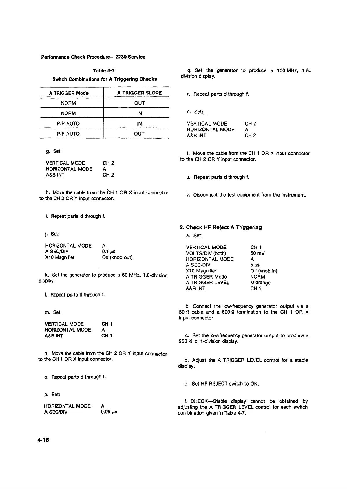
Table 4-7
Switch Combinations for A Triggering Checks
A TRIGGER Mode
A TRIGGER SLOPE
NORM
OUT
NORM IN
P-P AUTO IN
P-P AUTO
OUT
g. Set:
VERTICAL MODE CH 2
HORIZONTAL MODE A
A&B INT CH 2
h. Move the cable from the CH 1 OR X input connector
to the CH 2 OR Y input connector.
i. Repeat parts d through f.
). Set:
HORIZONTAL MODE A
A SEC/DIV 0.1 ns
XI0 Magnifier On (knob out)
k. Set the generator to produce a 60 MHz, 1.0-division
display.
l. Repeat parts d through f.
m. Set:
VERTICAL MODE CH 1
HORIZONTAL MODE A
A&B INT CH 1
n. Move the cable from the CH 2 OR Y input connector
to the CH 1 OR X input connector.
q. Set the generator to produce a 100 MHz, 1.5-
division display.
r. Repeat parts d through f.
s. Set:
VERTICAL MODE CH 2
HORIZONTAL MODE A
A&B INT CH 2
t. Move the cable from the CH 1 OR X input connector
to the CH 2 OR Y input connector.
u. Repeat parts d through f.
v. Disconnect the test equipment from the instrument.
2. Check HF Reject A Triggering
a. Set:
VERTICAL MODE CH 1
VOLTS/DIV (both) 50 mV
HORIZONTAL MODE A
A SEC/DIV 5 ns
X I0 Magnifier Off (knob in)
A TRIGGER Mode NORM
A TRIGGER LEVEL Midrange
A&B INT CH1
b. Connect the low-frequency generator output via a
50 Q cable and a 600 0 termination to the CH 1 OR X
input connector.
c. Set the low-frequency generator output to produce a
250 kHz, 1-division display.
d. Adjust the A TRIGGER LEVEL control for a stable
display.
o. Repeat parts d through f.
e. Set HF REJECT switch to ON.
p. Set:
HORIZONTAL MODE A
A SEC/DIV 0.05 ms
f. CHECK—Stable display cannot be obtained by
adjusting the A TRIGGER LEVEL control for each switch
combination given in Table 4-7.
4-18