Adjustment Procedure—2230 Service
f. Set the A&B INT switch to CH 2.
g. Repeat parts c through f until there is 1 mV or less
difference in the voltmeter readings between the CH 1 and
CH 2 positions of the A&B INT switch.
h. Disconnect the test equipment from the instrument.
2. Adjust A and B Trigger Sensitivity
(R471 and R627)
a. Set:
VERTICAL MODE CH 1
CH 1 VOLTS/DIV 0.1 V
AC-GND-DC (both) AC
ASEC/DIV 10 Ms
b. Connect the leveled sine-wave generator output via
a 50 0 cable and a 50 Q termination to the CH 1 OR X
input connector.
c. Set the generator to produce a 50 kHz, 2.2-division
display.
d. Set the CH 1 VOLTS/DIV switch to 1 V.
e. ADJUST—Trig Sens (R471) while rotating the A
TRIGGER LEVEL control slowly so that the A Trigger is
just able to be maintained.
f. Set the HORIZONTAL MODE switch to B.
g. ADJUST—B Trig Sens (R627) while rotating the B
TRIGGER LEVEL control slowly so that the B Trigger is
just able to be maintained.
3. Adjust P-P Auto Level (R434 and R435)
a. Set:
CH 1 VOLTS/DIV 50 mV
A TRIGGER SLOPE OUT
A TRIGGER LEVEL Fully clockwise
b. Set the leveled sine-wave generator to produce a
50 kHz, 6-division display.
c. Set the CH 1 VOLTS/DIV switch to 0.5 V.
d. ADJUST—(+) P-P Auto Level (R434) so that the
vertical display just solidly triggers on the positive peak of
the signal.
e. Set:
A TRIGGER SLOPE IN
A TRIGGER LEVEL Fully counterclockwise
f. ADJUST—(—) P-P Auto Level (R435) so that the
display just solidly triggers on the negative peak of the
signal.
g. Disconnect the test equipment from the instrument.
4. Check Internal A and B Triggering
a. Set:
CH 1 VOLTS/DIV 5 mV
CH 2 VOLTS/DIV 50 mV
HORIZONTAL MODE A
A and B SEC/DIV 0.2
A&B INT CH 1
A SOURCE INT
b. Connect the leveled sine-wave generator output via
a 50 fl cable and a 50 Q termination to the CH 1 OR X
input connector.
c. Set the generator to produce a 10 MHz, 3-division
display.
d. Set the CH 1 VOLTS/DIV switch to 50 mV.
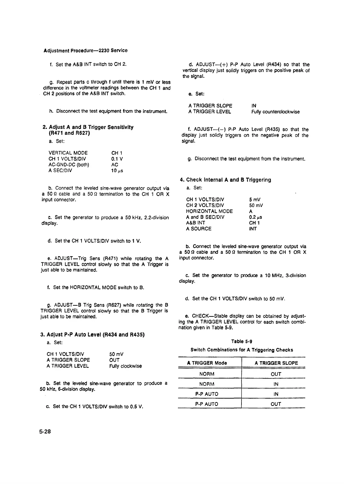
e. CHECK—Stable display can be obtained by adjust
ing the A TRIGGER LEVEL control for each switch combi
nation given in Table 5-9.
Table 5-9
Switch Combinations for A Triggering Checks
A TRIGGER Mode
A TRIGGER SLOPE
NORM
OUT
NORM
IN
P-P AUTO IN
P-P AUTO
OUT
5-28