Options—2230 Service
Message Terminator
As previously explained, GPIB messages may be ter
minated with either EOI or LF. Some controllers assert
EOI concurrently with the last data byte; others use only
the LF character as a terminator. The GPIB interface can
be set to accept either terminator. With EOI selected, the
instrument interprets a data byte received with EOI
asserted as the end of the input message; it also asserts
EOI concurrently with the last byte of an output message.
With the LF setting, the instrument interprets the LF char
acter without EOI asserted (or any data byte received with
EOI asserted) as the end of an input message; it transmits
a Carriage Return character followed by Line Feed (LF
with EOI asserted) to terminate output messages.
RS-232-C messages may be terminated with either car
riage return (CR) or the CR and Line-Feed (LF) characters.
The RS-232-C Option can be set to accept either termina
tor. With CR selected, the instrument interprets a line end
ing in CR as the end of the input message: it also sends
CR as the last byte of an output message. With the CR
and LF setting, the instrument interprets either the CR
character or the LF character as the end of an input mes
sage; it transmits a Carriage return character followed by
a Line Feed to terminate output messages.
Numeric Arguments
Many commands have numeric arguments. The
numeric arguments are shown in either <NR1>,
<NR2>, or <NR3> notation. These symbols refer to the
format of the numeric argument. All values must be
decimal (base 10).
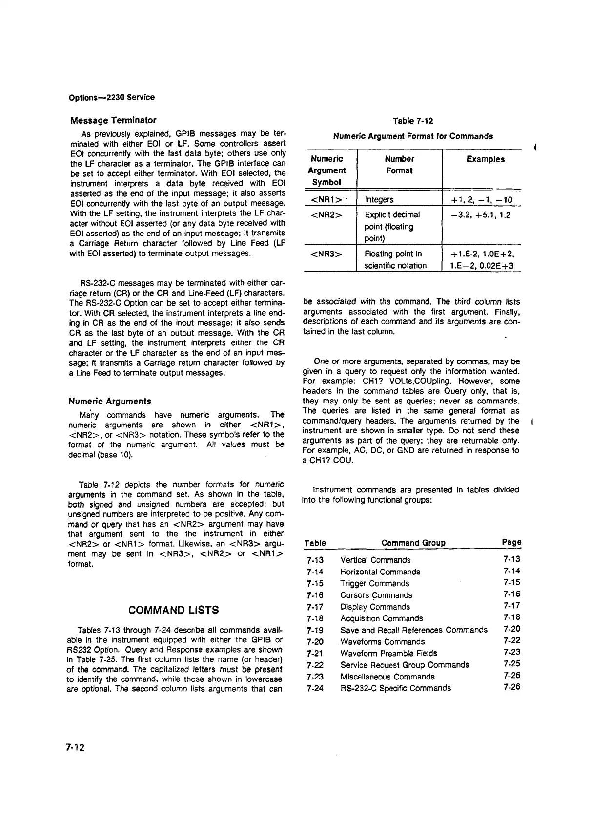
Table 7-12 depicts the number formats for numeric
arguments in the command set. As shown in the table,
both signed and unsigned numbers are accepted; but
unsigned numbers are interpreted to be positive. Any com
mand or query that has an <NR2> argument may have
that argument sent to the the instrument in either
<NR2> or <NR1> format. Likewise, an <NR3> argu
ment may be sent in <NR3>, <NR2> or <NR1>
format.
COMMAND LISTS
Tables 7-13 through 7-24 describe all commands avail
able in the instrument equipped with either the GPIB or
RS232 Option. Query and Response examples are shown
in Table 7-25. The first column lists the name (or header)
of the command. The capitalized letters must be present
to identify the command, while those shown in lowercase
are optional. The second column lists arguments that can
Table 7-12
Numeric Argument Format for Commands
Numeric
Argument
Symbol
Number
Format
Examples
<NR1> -
Integers + 1,2, -1 , -1 0
<NR2> Explicit decimal
point (floating
point)
-3.2, +5.1,1.2
<NR3>
Floating point in
+ 1.E-2,1.0E+2,
scientific notation
1.E-2, 0.02E+3
be associated with the command. The third column lists
arguments associated with the first argument. Finally,
descriptions of each command and its arguments are con
tained in the last column.
One or more arguments, separated by commas, may be
given in a query to request only the information wanted.
For example: CHI? VOLts,coupling. However, some
headers in the command tables are Query only, that is,
they may only be sent as queries; never as commands.
The queries are listed in the same general format as
command/query headers. The arguments returned by the |
instrument are shown in smaller type. Do not send these
arguments as part of the query; they are returnable only.
For example, AC, DC, or GND are returned in response to
a CHI? COU.
Instrument commands are presented in tables divided
into the following functional groups:
Table Command Group
Page
7-13
Vertical Commands
7-13
7-14
Horizontal Commands
7-14
7-15
Trigger Commands
7-15
7-16
Cursors Commands
7-16
7-17
Display Commands
7-17
7-18
Acquisition Commands
7-18
7-19
Save and Recall References Commands
7-20
7-20 Waveforms Commands
7-22
7-21 Waveform Preamble Fields
7-23
7-22 Service Request Group Commands
7-25
7-23
Miscellaneous Commands
7-26
7-24
RS-232-C Specific Commands
7-26
7-12