AIR FORCE
T033A1-13-496-1
NAVE
LEX
0969-LP-170-0010
Maintenance Instructions
NOTE
(5)
Semiconductor
Lead Configurations.
Typical
semiconductor
lead configurations are
shown in Figure
5-3.
b.
Troubleshooting
Techniques. The following pro-
cedures are
arranged in an order that checks the simple
trouble
possibilities
before
proceeding with extensive
troubleshooting.
The first few checks ensure proper con-
nection,
operation, and calibration.
If the trouble is not
located by
these checks, the remaining
checks should aid
in
locating the defective component.
(1)
Check
Control
Settings. Incorrect control settings
can
indicate
a
trouble that does not
exist.
If
there is any
question about the correct function
or operation of any
control,
see
the Operation Instructions section.
(2)
Check Associated Equipment. Before proceeding
with
troubleshooting, check
that the equipment used with
this instrument is operating correctly.
Check that the signal
is
properly connected and
that the interconnecting
cables
are not defective. Also,
check the power
source.
(3)
Check
Instrument Calibration.
Check
the cali-
bration of
this
instrument,
or the affected
circuit if
the
trouble exists in one circuit.
The apparent
trouble may
only be misadjustment
that can be
corrected
by
calibration.
(4)
Visual Check. Visually
check
the portion of the
instrument in
which the trouble
is located.
Many troubles
can
be located
by
visual
indications
such
as
unsoldered
con-
nections, broken wires,
damaged
circuit boards,
and dam-
aged
components.
(5)
Isolate
Trouble
to a Circuit.
Using the trouble-
shooting
chart Figure
5-2,
isolate trouble
to a
particular
circuit.
The
symptom often
identifies
the defective
circuit.
Trouble
appearing
in more
than one
circuit can
indicate
possible
power
supply problems.
Power
supply tolerance
and
ripple limits
can
be checked
using Table
5-5.
Power
supply
disconnect
jumpers
are provided
for each of
the
sup-
plies. Refer
to the
schematics and
circuit
board illustrations
for their
location.
These
jumpers can be
unsoldered
to
dis-
connect
the circuit
load from
most of
the supplies.
Each
unregulated supply
contains
a fuse
for
circuit
protection.
(6)
Check
Circuit
Board
Interconnections.
After
the
trouble
has been
isolated
to a
particular circuit,
check
for
loose
or broken
connections,
improperly
seated
transistors
and
heat
damaged
components.
(7)
Check
Voltages
and
Waveforms.
Often the
de-
fective
component
can
be
located
by checking
for
the
correct
voltage
or
waveform
in
the
circuit.
Typical
volt-
ages
are
given
on
the
diagrams.
Waveforms
are
shown on
the
circuit
diagram
apron.
Voltages
and waveforms given
on the
diagrams are
not
absolute and therefore
may vary
slightly
be-
tween
instruments.
To
obtain
operating
conditions
similar
to
those
used to take
these readings,
see the
voltage and
waveform
set up procedures
in the
Diagrams
section.
Individual deviations
should
be noted
on the
schematics for future
reference.
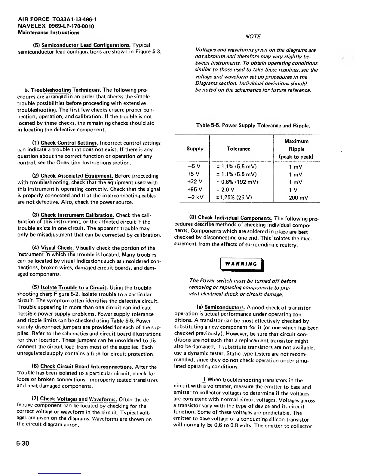
Table
5-5.
Power
Supply
Tolerance
and Ripple.
Supply
Tolerance
Maximum
Ripple
(peak
to peak)
-5
V ±
1.1%
(5.5
mV)
1 mV
+5
V
±1.1%
(5.5
mV)
1 mV
+32
V
±0.6%
(192
mV)
1 mV
+95
V ±
2.0 V
1 V
-2
kV
±1.25%
(25
V)
200
mV
(8) Check
Individual
Components.
The
following
pro-
cedures
describe
methods
of
checking
individual
compo-
nents.
Components
which
are
soldered
in
place
are
best
checked
by
disconnecting
one
end.
This
isolates
the
mea-
surement
from
the
effects
of
surrounding
circuitry.
WARNING
The
Power
switch
must be
turned
off
before
removing
or
replacing
components
to
pre-
vent
electrical
shock
or circuit
damage.
(a)
Semiconductors.
A good
check
of
transistor
operation
is
actual
performance
under
operating
con-
ditions.
A
transistor
can be
most
effectively
checked
by
substituting
a
new
component
for
it (or
one which
has
been
checked
previously).
However,
be
sure that
circuit
con-
ditions
are
not
such
that
a replacement
transistor
might
also
be
damaged.
If
substitute
transistors
are
not
available,
use
a
dynamic
tester.
Static
type
testers are
not recom-
mended,
since
they
do
not check
operation
under
simu-
lated
operating
conditions.
When
troubleshooting
transistors
in
the
circuit
with
a
voltmeter,
measure
the
emitter
to
base and
emitter
to
collector
voltages
to
determine
if
the
voltages
are
consistent
with
normal
circuit
voltages.
Voltages
across
a transistor
vary
with
the
type of device
and its
circuit
function.
Some of
these
voltages
are
predictable.
The
emitter
to base
voltage
of
a
conducting
silicon
transistor
will
normally
be
0.6
to
0.8 volts.
The
emitter
to
collector
5-30