AIR FORCE T033A1
-13-496-1
NAVELEX
0969-LP-170-0010
Operation Instructions
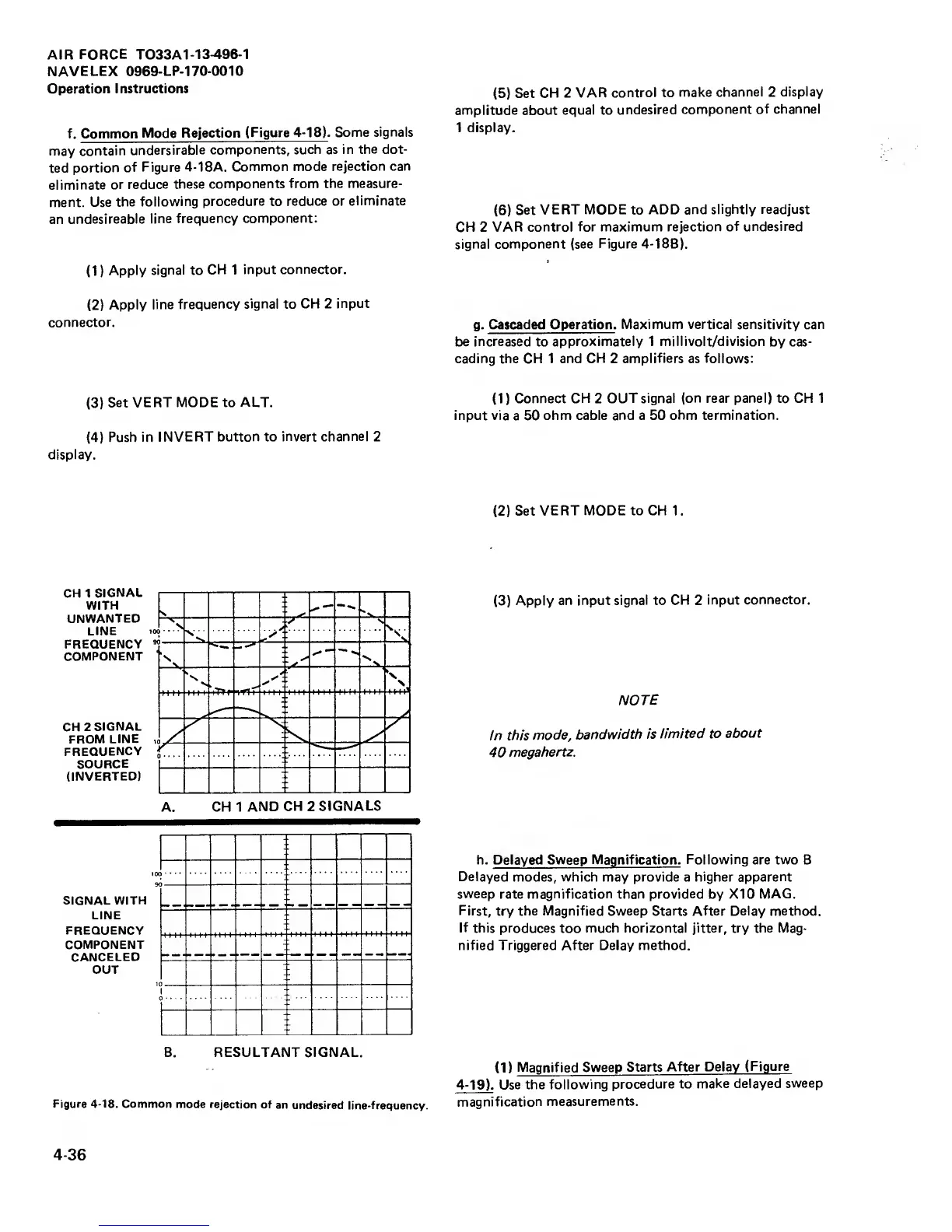
f. Common
Mode Rejection
(Figure
4-18).
Some
signals
may contain
undersirable
components, such as in
the
dot-
ted
portion
of
Figure
4-1
8A.
Common mode
rejection can
eliminate
or reduce
these
components
from the measure-
ment. Use
the
following
procedure
to
reduce or
eliminate
an
undesireable
line
frequency component:
(1
)
Apply
signal
to
CH
1
input
connector.
(2)
Apply
line
frequency
signal
to
CH 2
input
connector.
(3)
Set VERT
MODE
to
ALT.
(4)
Push in
INVERT button to
invert channel
2
display.
(5)
Set
CH 2 VAR
control to
make
channel
2
display
amplitude about equal to
undesired
component
of channel
1 display.
(6)
Set
VERT MODE
to
ADD and
slightly readjust
CH 2 VAR
control for maximum rejection
of undesired
signal
component (see
Figure
4-1
SB).
g.
Cascaded Operation.
Maximum vertical sensitivity can
be
increased
to
approximately 1 millivolt/division
by cas-
cading the CH 1 and
CH
2
amplifiers
as follows:
(1)
Connect CH
2
OUT signal
(on
rear panel) to
CH
1
input via
a 50
ohm cable and a 50 ohm
termination.
(2)
Set
VERT MODE to
CH
1.
CH
1
SIGNAL
WITH
UNWANTED
LINE
FREQUENCY
COMPONENT
CH
2
SIGNAL
FROM
LINE
FREQUENCY
SOURCE
(INVERTED)
A. CH 1
AND
CH
2
SIGNALS
SIGNAL WITH
LINE
FREQUENCY
COMPONENT
CANCELED
OUT
B. RESULTANT SIGNAL.
Figure
4-18.
Common mode
rejection of
an
undesired line-frequency.
(3)
Apply
an input signal to
CH
2
input
connector.
NOTE
In
this
mode,
bandwidth is
limited to
about
40
megahertz.
h. Delayed Sweep Magnification.
Following
are two B
Delayed
modes, which may provide a
higher
apparent
sweep
rate
magnification
than
provided
by XI 0
MAG.
First,
try
the Magnified Sweep Starts After Delay method.
If
this produces
too
much horizontal jitter, try the Mag-
nified Triggered After Delay method.
(1)
Magnified Sweep
Starts
After Delay
(Figure
4-19). Use the
following
procedure to
make delayed
sweep
magnification
measurements.
4-36