AIR
FORCE T033A1
-13-496-1
NAVE LEX
0969-LP-1
70-0010
Operation
Instructions
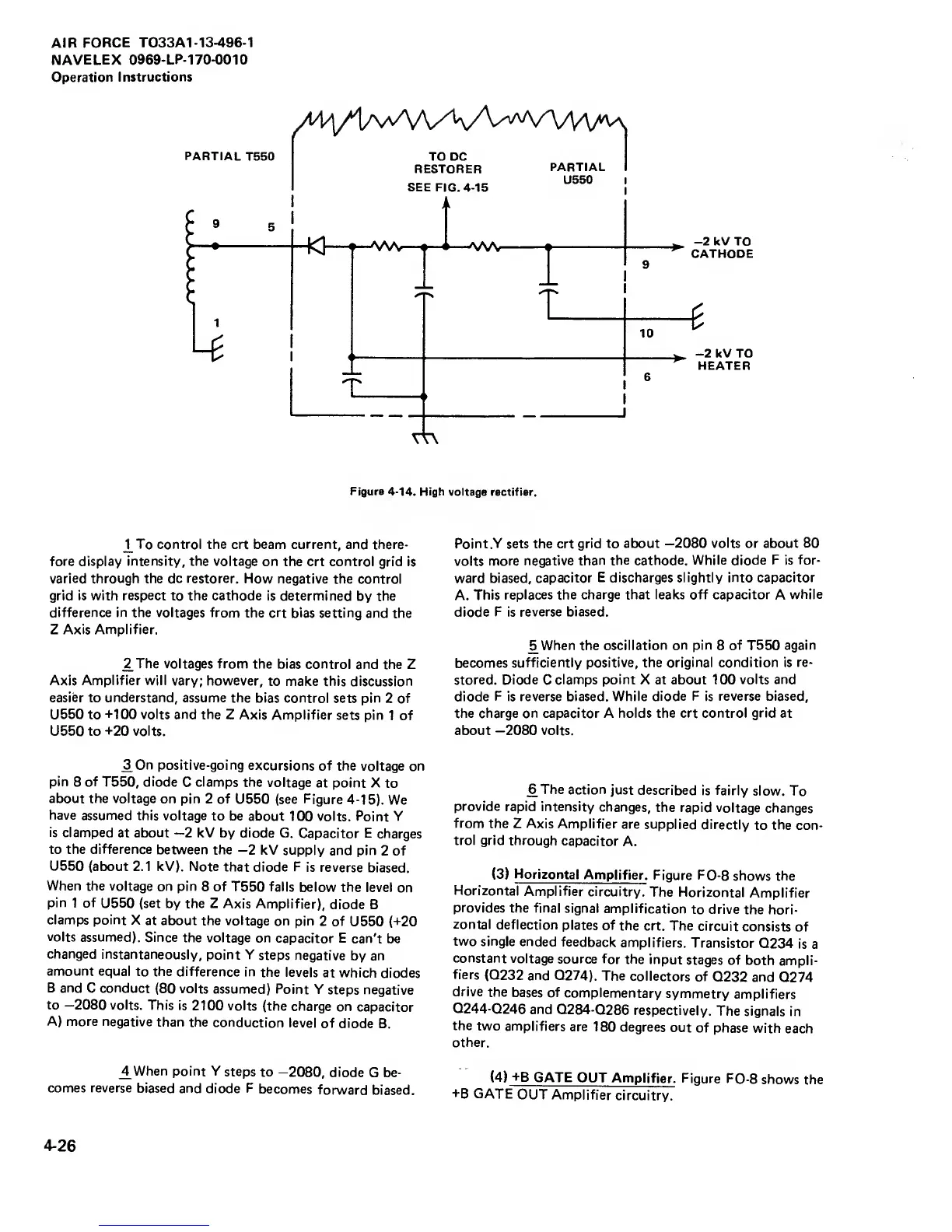
Figure 4-14.
High
voltage rectifier.
J^To
control the
crt
beam current,
and there-
fore display intensity,
the
voltage
on
the
crt control grid is
varied through the dc restorer. How negative
the control
grid is
with respect
to the cathode is determined
by
the
difference in the voltages from
the crt bias setting
and the
Z Axis Amplifier,
^The voltages from
the bias control
and the Z
Axis Amplifier will
vary; however,
to make this discussion
easier to understand, assume the
bias control
sets
pin
2 of
U550 to
+100
volts and the
Z Axis Amplifier
sets pin
1 of
U550 to
+20
volts.
^On positive-going
excursions of the
voltage on
pin
8
of
T550,
diode
C
clamps the
voltage
at point X
to
about the voltage
on pin 2 of
U550 (see Figure
4-15).
We
have assumed
this voltage
to be about
100 volts. Point Y
is
clamped
at
about
—2
kV by diode G.
Capacitor
E
charges
to the difference
between the
—2
kV supply
and pin
2 of
U550
(about 2.1 kV). Note
that diode
F
is reverse
biased.
When
the voltage
on pin
8 of T550 falls
below the
level on
pin
1
of
U550
(set
by the Z
Axis Amplifier),
diode
B
clamps point
X
at about the voltage
on pin
2 of
U550 (+20
volts assumed).
Since
the voltage
on
capacitor
E
can't
be
changed
instantaneously,
point Y
steps
negative
by an
amount equal
to the difference
in
the levels
at which
diodes
B and
C conduct
(80
volts
assumed)
Point Y
steps negative
to
—2080
volts.
This
is 2100 volts
(the charge
on
capacitor
A) more
negative
than the
conduction
level
of diode
B.
^When point Y
steps
to
-2080, diode
G be-
comes reverse
biased and
diode
F
becomes
forward biased.
Point
,Y
sets
the crt grid to about
—2080
volts
or
about 80
volts
more
negative than
the cathode. While diode
F
is
for-
ward biased,
capacitor
E discharges slightly into capacitor
A.
This replaces the
charge that leaks off capacitor
A
while
diode
F
is
reverse biased.
^When the
oscillation on pin
8
of
T550
again
becomes
sufficiently positive, the original condition is
re-
stored. Diode
C
clamps
point
X at about 100
volts and
diode
F
is reverse biased. While
diode F
is
reverse biased,
the charge on capacitor A holds the crt control
grid
at
about
—2080
volts.
^The action
just
described
is
fairly
slow. To
provide
rapid intensity
changes,
the rapid
voltage
changes
from
the Z Axis
Amplifier
are
supplied directly
to
the
con-
trol grid through
capacitor
A.
(3)
Horizontal
Amplifier.
Figure
FO-8
shows the
Horizontal
Amplifier
circuitry.
The
Horizontal
Amplifier
provides
the final
signal
amplification
to drive
the hori-
zontal
deflection
plates of
the
crt. The
circuit
consists
of
two single
ended
feedback
amplifiers.
Transistor
Q234
is
a
constant
voltage source
for the
input
stages
of both
ampli-
fiers
(Q232 and
Q274). The
collectors
of
Q232 and
Q274
drive
the
bases of
complementary
symmetry
amplifiers
Q244-Q246
and Q284-Q286
respectively.
The signals
in
the
two
amplifiers
are 180
degrees
out
of phase
with
each
other.
(4)
+B
GATE
OUT
Amplifier.
Figure
FO-8
shows
the
+B GATE
OUT Amplifier
circuitry.
4-26