AIR
FORCE T033A1
-13-496-1
NAVELEX
0969-LP-170-0010
Maintenance
Instructions
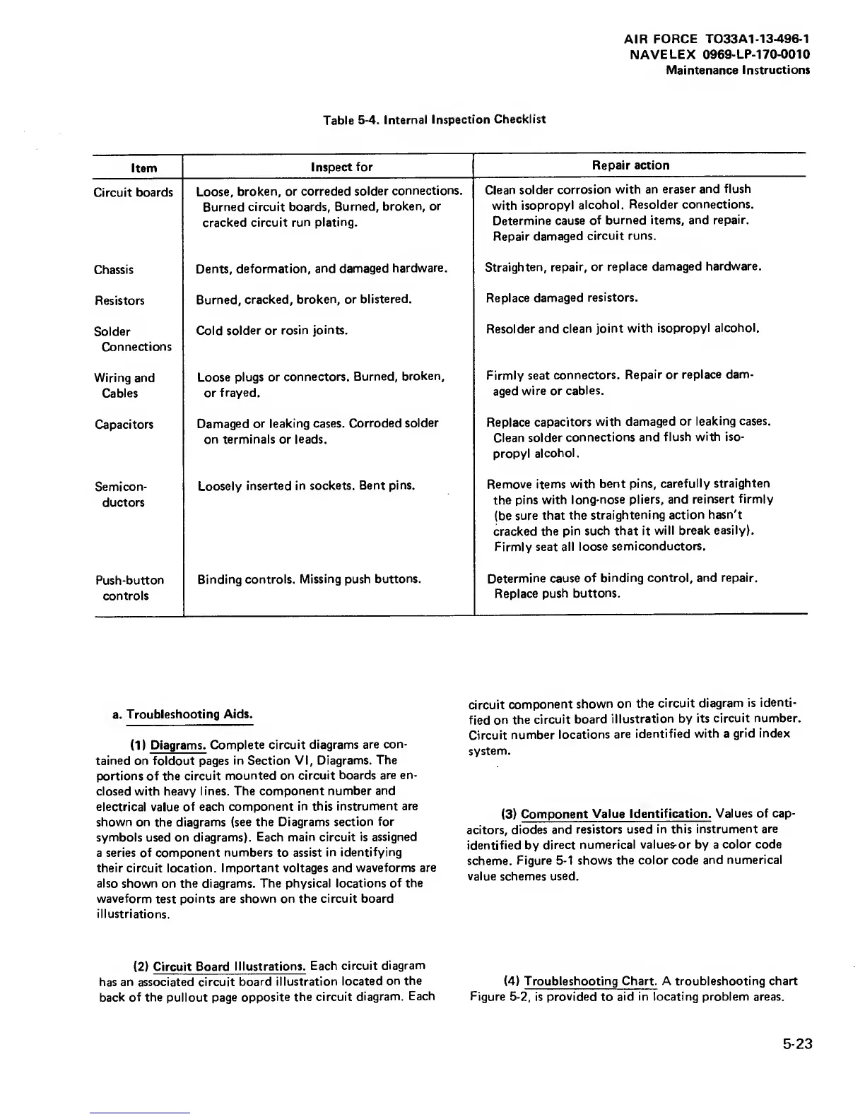
Table
5-4.
Internal
Inspection
Checklist
Item
Inspect
for
Repair action
Circuit
boards
Loose,
broken, or correded
solder
connections.
Burned circuit boards.
Burned,
broken,
or
cracked circuit
run plating.
Clean solder
corrosion
with an
eraser and
flush
with
isopropyl
alcohol.
Resolder
connections.
Determine
cause of
burned items,
and repair.
Repair
damaged
circuit runs.
Chassis
Dents,
deformation,
and damaged
hardware.
Straighten,
repair,
or
replace damaged
hardware.
Resistors
Burned,
cracked,
broken, or
blistered.
Replace
damaged
resistors.
Solder
Connections
Cold solder or
rosin
joints.
Resolder
and clean
joint
with isopropyl
alcohol.
Wiring and
Cables
Loose plugs
or
connectors.
Burned,
broken,
or
frayed.
Firmly seat
connectors.
Repair
or
replace
dam-
aged
wire or
cables.
Capacitors
Damaged
or
leaking cases.
Corroded solder
on terminals or
leads.
1
Replace
capacitors
with
damaged or
leaking cases.
Clean
solder
connections
and flush
with iso-
propyl
alcohol.
Semicon-
ductors
Loosely
inserted
in sockets. Bent
pins.
Remove items
with
bent pins,
carefully
straighten
the
pins
with
long-nose pliers,
and reinsert
firmly
(be
sure that
the
straightening action
hasn't
cracked the
pin
such that it
will break
easily).
Firmly
seat all
loose
semiconductors.
Push-button
controls
Binding
controls. Missing
push buttons.
Determine
cause of
binding control,
and repair.
Replace
push buttons.
a.
Troubleshooting
Aids.
(1)
Diagrams.
Complete circuit diagrams
are
con-
tained
on foldout pages
in Section VI,
Diagrams. The
portions of the
circuit
mounted on circuit
boards are en-
closed with heavy
lines. The
component number
and
electrical
value
of each
component in this
instrument are
shown on
the diagrams
(see the Diagrams
section for
symbols
used on
diagrams). Each main circuit
is assigned
a series of component
numbers
to
assist in
identifying
their circuit location.
Important voltages and waveforms
are
also shown
on
the diagrams. The physical
locations of the
waveform
test
points are shown on the circuit board
illustriations.
(2)
Circuit Board
Illustrations.
Each circuit
diagram
has an associated circuit
board
illustration
located
on the
back of the
pullout
page
opposite the circuit
diagram.
Each
circuit
component
shown
on the
circuit
diagram is
identi-
fied
on
the
circuit
board
illustration
by its
circuit
number.
Circuit
number
locations
are
identified with a
grid index
system.
(3)
Component
Value
Identification. Values of cap-
acitors,
diodes
and resistors
used in this
instrument are
identified by
direct
numerical values-or by a
color code
scheme.
Figure
5-1
shows the color code
and numerical
value schemes
used.
(4)
Troubleshooting Chart. A troubleshooting chart
Figure
5-2, is
provided
to
aid in locating problem areas.
5-23