AIR
FORCE T033A1-13-496-1
NAVELEX
0969-LP-170-0010
Operation
Instructions
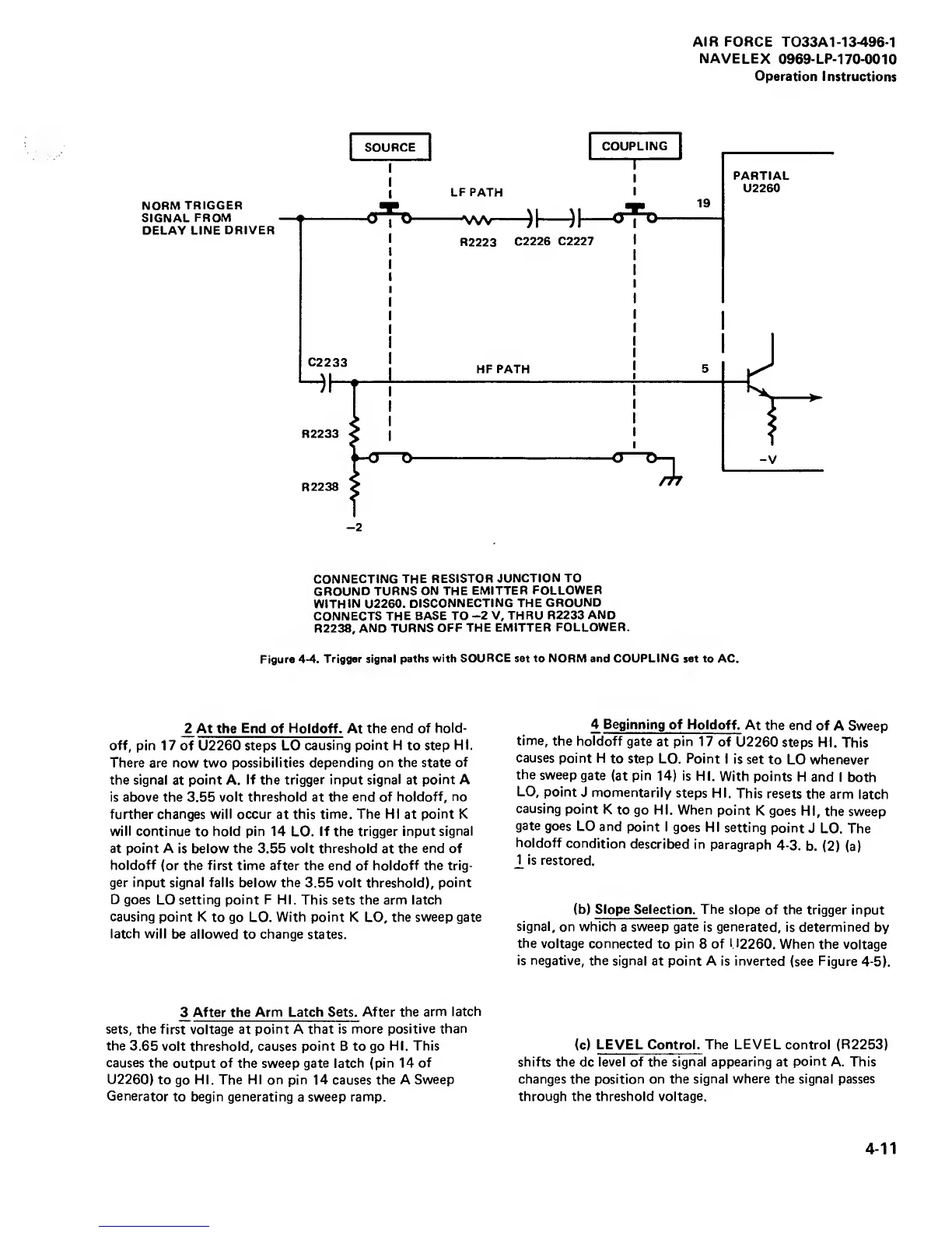
NORM
TRIGGER
SIGNAL
FROM
DELAY
LINE DRIVER
CONNECTING
THE
RESISTOR
JUNCTION TO
GROUND
TURNS ON
THE
EMITTER FOLLOWER
WITHIN
U2260.
DISCONNECTING THE
GROUND
CONNECTS
THE BASE TO
-2
V, THRU R2233
AND
R2238,
AND
TURNS OFF
THE EMITTER
FOLLOWER.
Figure
4-4.
Trigger signal
paths with
SOURCE set to
NORM and COUPLING set
to AC.
2 At the
End
of Holdoff. At the
end of hold-
off,
pin 17 of
U2260
steps LO
causing point H
to
step
HI.
There are now two
possibilities depending on the state
of
the signal
at
point A.
If the trigger input signal
at
point A
is above the 3.55 volt
threshold
at
the end of holdoff,
no
further changes will occur
at
this time. The HI at
point
K
will continue
to
hold pin 14
LO.
If the trigger input
signal
at point A is below the 3.55 volt threshold
at
the end of
holdoff
(or the first time
after
the end of holdoff the trig-
ger input
signal
falls below the
3.55 volt threshold),
point
D goes
LO
setting point F HI.
This sets the arm latch
causing
point K
to go LO.
With point
K LO,
the sweep gate
latch will
be allowed to change states.
3
After
the
Arm Latch Sets.
After the
arm
latch
sets, the
first voltage at
point
A
that is more
positive
than
the 3.65
volt threshold, causes point B to go
HI. This
causes
the
output
of
the sweep
gate latch (pin 14
of
U2260)
to
go
HI. The HI on pin 14 causes the A
Sweep
Generator
to begin generating
a
sweep ramp.
4 Beginning
of Holdoff.
At the
end
of A Sweep
time, the
holdoff
gate
at
pin 17
of
U2260 steps
HI.
This
causes
point H
to
step
LO. Point
I is set
to
LO whenever
the
sweep
gate
(at
pin
14)
is
HI.
With points
H
and I
both
LO,
point
J momentarily
steps
HI.
This resets
the arm
latch
causing
point
K
to go
HI.
When
point
K goes
HI,
the sweep
gate
goes
LO and
point
I goes
HI setting
point
J
LO. The
holdoff
condition
described
in
paragraph
4-3.
b.
(2)
(a)
2
is
restored.
(b) Slope Selection. The
slope of the trigger input
signal, on
which
a
sweep gate is generated,
is determined
by
the
voltage connected
to pin
8
of
1.
12260. When the voltage
is negative,
the signal
at point A is inverted
(see
Figure
4-5).
(c)
LEVEL Control. The
LEVEL
control
(R2253)
shifts the
dc
level of the signal
appearing
at
point
A. This
changes the position on the
signal where
the
signal passes
through the threshold
voltage.
4-11