AIR FORCE
T033A1-13-496-1
NAVELEX 0969-LP-1 70-0010
Maintenance Instructions
Table
5-1.
Operational Checkout
Procedures—
Continued
Step
Procedure
Normal Indication
5
(con-
tinued)
c.
Set
the calibration generator for
20
mV (INTEN may need
to
be
increased).
3.88 to
1.12 division
horizontal
display.
d. Set
CH
1
AC-GND-DC
to AC.
3.88
to 1.12 division
horizontal
display.
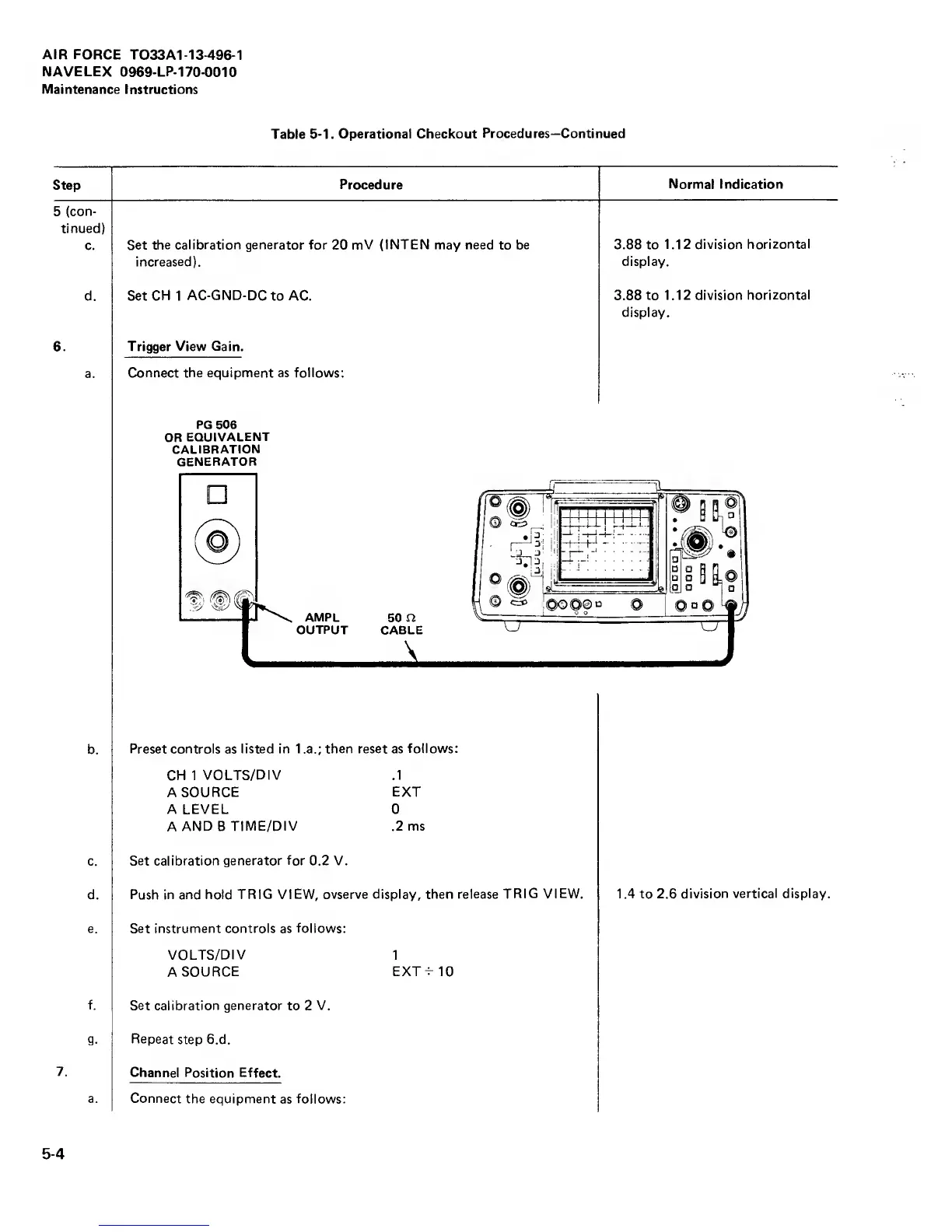
6. Trigger
View Gain.
a.
Connect the equipment as follows;
PG 506
OR
EQUIVALENT
CALIBRATION
GENERATOR
b.
Preset controls
as
listed in 1
.a.;
then reset as
follows:
CH 1
VOLTS/DIV .1
A
SOURCE
EXT
A LEVEL 0
A
AND B
TIME/DIV .2 ms
c.
Set calibration generator for 0.2 V.
d.
Push in and hold TRIG
VIEW, ovserve display, then
release TRIG
VIEW,
1.4 to 2.6 division
vertical display.
e. Set instrument controls as
follows:
VOLTS/DIV
1
A
SOURCE
EXT^IO
f.
Set calibration generator
to 2
V.
g.
Repeat
step 6.d.
7.
Channel Position Effect.
a. Connect
the equipment
as
follows;
5-4