AIR
FORCE
T033A1-13-496-1
NAVE
LEX
0969-LP-1 70-0010
Maintenance
Instructions
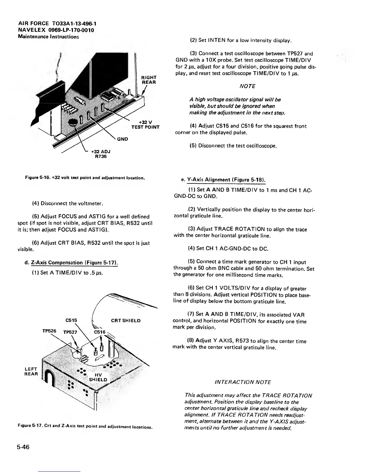
R736
Figure
5-16.
-*-32
volt test
point and
adjustment location.
(4)
Disconnect the voltmeter.
(5)
Adjust FOCUS
and
ASTIG for
a well defined
spot (if spot is not visible,
adjust
CRT
BIAS, R532 until
it is; then adjust FOCUS and ASTIG).
(6)
Adjust CRT BIAS, R532
until the
spot
is
just
visible.
d. Z-Axis Compensation
(Figure 5-17).
(l)Set
A
TIME/DI
V to
.5
ms.
Figure 5-17.
Crt
and
Z-Axis
test
point
and
adjustment
iocations.
(2)
Set INTEN for
a low intensity
display.
(3)
Connect
a
test oscilloscope
between TP527
and
GND with
a 10X probe. Set test oscilloscope
TIME/DIV
for
2
MS,
adjust
for
a
four division,
positive
going pulse
dis-
play, and reset test oscilloscope
TIME/DIV
to
1 ms.
NOTE
A high voltage oscillator
signal will
be
visible,
but should be ignored
when
making the
adjustment in the next
step.
(4)
Adjust
C515
and
C516
for
the
squarest front
corner on
the displayed pulse.
(5)
Disconnect the
test oscilloscope.
e.
Y-Axis
Alignment
(Figure 5-18).
(1)
Set
A AND
B TIME/DIV
to 1 ms
and CH
1
AC-
GND-DCto
GND.
(2)
Vertically
position the
display
to the
center
hori-
zontal
graticule
line.
(3)
Adjust
TRACE
ROTATION
to align
the
trace
with
the center
horizontal
graticule line.
(4)
Set
CH
1 AC-GND-DC
to DC.
(5)
Connect
a time mark
generator
to CH
1 input
through
a 50
ohm BNC
cable and
50 ohm
termination.
Set
the
generator
for
one
millisecond
time
marks.
(6)
Set CH
1 VOLTS/DIV
for
a display
of
greater
than
8 divisions.
Adjust vertical
POSITION
to place
base-
line
of
display
below
the
bottom
graticule
line.
(7)
Set
A AND
B TIME/DIV,
its
associated
VAR
control,
and
horizontal
POSITION
for
exactly
one
time
mark
per
division.
(8)
Adjust Y
AXIS,
R573
to align
the
center
time
mark
with
the
center
vertical
graticule
line.
INTERACTION
NOTE
This
adjustment may affect
the
TRACE
ROTATION
adjustment.
Position the
display baseline
to
the
center
horizontal
graticule line
and recheck
display
alignment,
if
TRACE ROTA
TION needs
readjust-
ment,
alternate
between it and
the Y-AXIS
adjust-
ments
until no
further adjustment
is
needed.
5-46
 Loading...


