AIR
FORCE
T033A1-13-496-1
NAVELEX
0969-LP-170-0010
Operation
Instructions
BEGINNING OF
HOLDOFF
A
SWEEP
RAMP
TP2797
HOLDOFF OUT
TP2750
HOLDOFF
TIMING
START OUT
PIN 10
OF
U2750
HOLDOFF
TIMING
RAMP
IN
PIN 11 OF
U2750
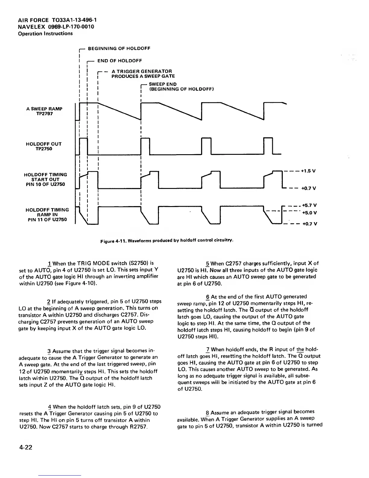
Figure
4-1
1 .
Waveforms
produced
by
holdoff
control
circuitry.
IWhen
the
TRIG
MODE switch
(S2750)
is
set
to
AUTO,
pin 4
of
U2750
is set LO.
This
sets input
Y
of the AUTO
gate logic
HI through
an
inverting
amplifier
within
U2750
(see
Figure
4-10).
2
If adequately
triggered,
pin
5
of U2750
steps
LO at
the
beginning of A
sweep
generation.
This turns on
transistor A
within
U2750
and
discharges C2757.
Dis-
charging
C2757
prevents
generation of an
AUTO
sweep
gate
by
keeping
input
X
of
the AUTO
gate logic LO.
3
Assume that
the
trigger
signal
becomes
in-
adequate
to
cause the A
Trigger
Generator to
generate
an
A sweep
gate. At
the end
of the last
triggered
sweep,
pin
12 of U2750
momentarily steps HI. This
sets the
holdoff
latch
within
U2750.
The Q output
of the holdoff
latch
sets
input
Z
of the AUTO gate logic
HI.
4
When
the holdoff latch sets, pin 9 of
U2750
resets the
A
Trigger Generator causing pin
5
of
U2750 to
step HI. The HI on pin
5
turns off transistor
A
within
U2750. Now
C2757
starts to charge through
R2757.
^When
C2757
charges
sufficiently, input X
of
U2750
is HI. Now
all three
inputs
of
the
AUTO gate
logic
are
HI which
causes an
AUTO sweep
gate
to
be
generated
at
pin
6
of U2750.
6
At
the end of the
first AUTO
generated
sweep ramp,
pin 12 of U2750
momentarily
steps HI, re-
setting the
holdoff latch.
The Q output
of the
holdoff
latch
goes LO,
causing the output
of the AUTO
gate
logic
to
step
HI. At the
same time, the Q output
of the
holdoff latch steps
HI,
causing holdoff
to
begin
(pin
9
of
U2750
steps HI).
1
_
When
holdoff
ends,
the R input of
the hold-
off
latch
goes HI,
resetting the holdoff latch.
The Q output
goes HI, causing the AUTO
gate
at
pin 6 of U2750 to
step
LO.
This causes
another AUTO sweep
to
be generated. As
long as no
adequate trigger
signal is available, all subse-
quent sweeps will be initiated by
the AUTO gate
at
pin
6
of U2750.
^Assume
an
adequate
trigger
signal
becomes
available.
wi7en A
Trigger
Generator
supplies
an
A
sweep
gate to
pin
5
of U2750,
transistor
A
within
U2750
is
turned
4-22