AIR
FORCE
T033A1
-13-496-1
NAVELEX
0969-LP-170-0010
Operation
Instructions
Table
4-2.
Functions
of
Control,
Connectors, and
Indicators—
Continued
Figure/index
no.
Control,
connector,
or
indicator
name
Function
FO-1/23
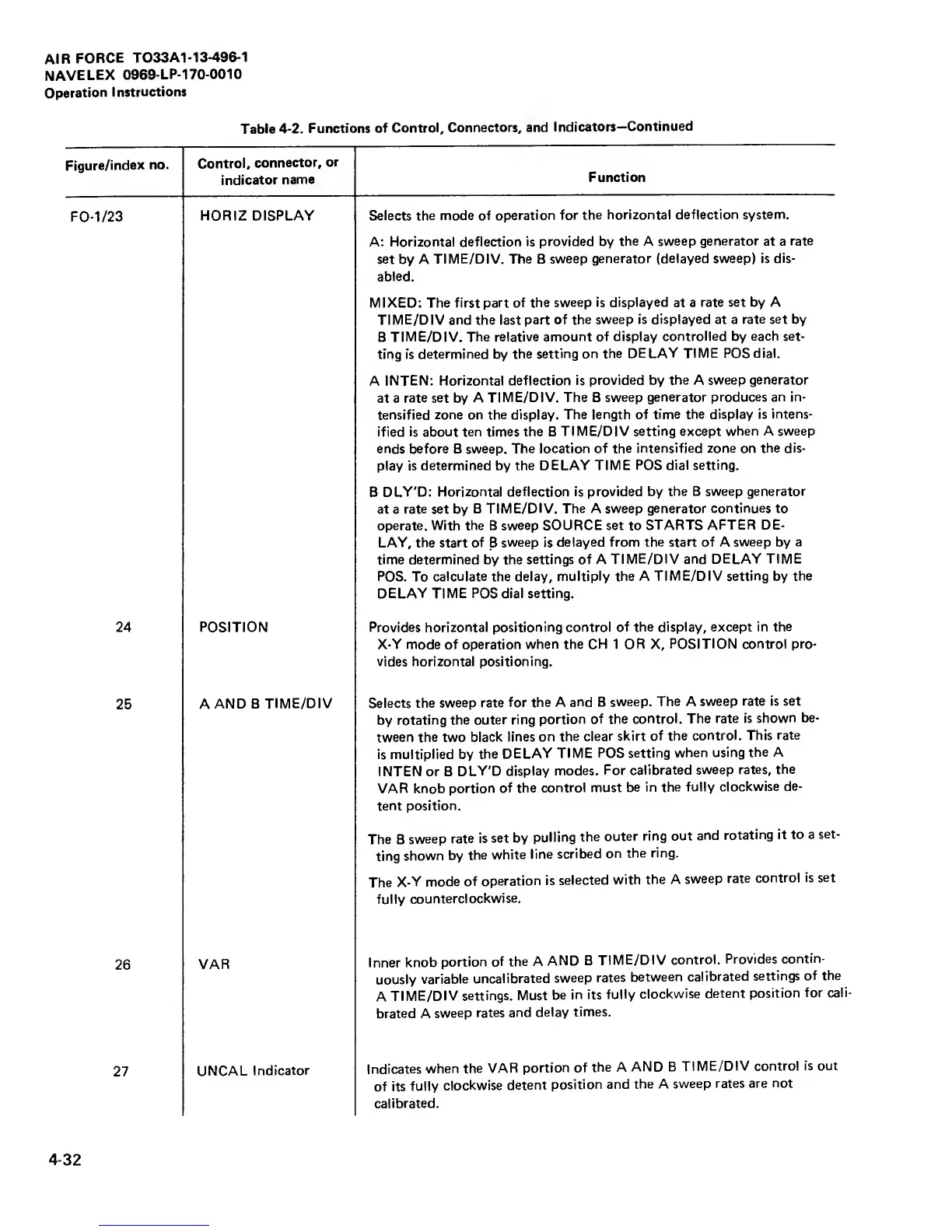
HORIZ DISPLAY Selects
the mode of
operation for
the horizontal
deflection system.
A: Horizontal deflection
is provided by
the A sweep
generator
at a
rate
set
by A
TIME/DIV.
The B
sweep
generator (delayed sweep) is
dis-
abled.
MIXED: The first
part of the
sweep is displayed
at a
rate set by A
TIME/DIV
and the last
part of the
sweep is displayed at a
rate set
by
B
TIME/DIV. The relative
amount of display
controlled
by
each set-
ting is
determined
by
the
setting on the
DELAY TIME POS dial.
A
INTEN: Horizontal
deflection is
provided
by
the
A
sweep generator
at a
rate set
by
A
TIME/DIV. The B
sweep generator produces
an in-
tensified
zone on the display. The
length of time the display is
intens-
ified is about ten times the B
TIME/DIV setting except
when A sweep
ends before B sweep.
The location of the
intensified zone on the dis-
play is
determined
by
the
DELAY TIME POS dial setting.
B
DLY'D: Horizontal
deflection is provided by
the
B
sweep generator
at a
rate set by B
TIME/DIV. The A sweep generator
continues
to
operate. With the
B
sweep SOURCE
set
to
STARTS
AFTER DE-
LAY,
the start
of
B
sweep
is
delayed
from the start of A sweep
by
a
time determined
by the
settings
of A
TIME/DIV and
DELAY TIME
POS. To
calculate
the delay,
multiply the A
TIME/DIV setting
by
the
DELAY TIME POS dial setting.
24
POSITION Provides horizontal positioning control
of the display, except in
the
X-Y
mode of operation
when the CH 1 OR X,
POSITION control pro-
vides horizontal positioning.
25
A
AND B
TIME/DIV
Selects the
sweep rate
for the A
and B
sweep.
The
A
sweep
rate is set
by
rotating the
outer ring
portion
of the
control.
The rate is
shown be-
tween the two
black lines
on the
clear skirt
of the
control. This
rate
is multiplied by
the
DELAY
TIME
POS setting
when using
the A
INTEN or B
DLY'D
display
modes.
For calibrated
sweep
rates, the
VAR knob
portion
of the
control must
be in the
fully
clockwise
de-
tent
position.
The
B
sweep
rate is
set by
pulling
the
outer ring
out
and
rotating
it
to a
set-
ting
shown by
the
white
line
scribed
on
the ring.
The
X-Y
mode
of
operation
is
selected
with
the A
sweep
rate
control is
set
fully
counterclockwise.
VAR
Inner
knob
portion of
the A
AND B
TIME/DIV
control.
Provides
contin-
uously
variable
uncalibrated
sweep
rates
between
calibrated
settings
of the
A
TIME/DIV
settings. Must
be
in its
fully
clockwise
detent
position
for cali-
brated A
sweep
rates
and
delay
times.
27
UNCAL
Indicator
Indicates
when the
VAR
portion
of
the A
AND B
TIME/DIV control
is out
of its
fully
clockwise
detent
position and
the A
sweep
rates are
not
calibrated.
4-32