Preface
Preface
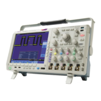
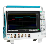
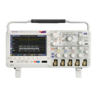
This manual describes the installation and operation of the following oscilloscopes:
Model Bandwidth
Analog
Channels
Sample
Rate (1 ch)
Sample
Rate (2 ch)
Sample
Rate (4 ch)
Record
Length
(1 ch)
Record
Length
(2 ch )
Record
Length
(4 ch)
MSO4104B 1 GHz
4
5 GS/s 5 GS/s 5 G S/s
20M 20M 20M
MSO4104B-L 1 GHz
4
5 GS/s 5 GS/s 2.5 GS/s
5M 5M 5M
MSO4102B 1 GHz
2
5GS/s 5GS/s
--
20M 20M
--
MSO4102B-L 1 GHz
2
5 GS/s 2.5 GS/s
--
5M 5M
--
MSO4054B
500 MHz 4
2.5 GS/s 2.5 GS/s 2.5 GS/s
20M 20M 20M
MSO4034B
350 MHz 4
2.5 GS/s 2.5 GS/s 2.5 GS/s
20M 20M 20M
MSO4014B
100 MHz 4
2.5 GS/s 2.5 GS/s 2.5 GS/s
20M 20M 20M
DPO4104B 1 GHz
4
5 GS/s 5 GS/s 5 G S/s
20M 20M 20M
DPO4104B-L 1 GHz
4
5 GS/s 5 GS/s 2.5 GS/s
5M 5M 5M
DPO4102B 1 GHz
2
5GS/s 5GS/s
--
20M 20M
--
DPO4102B-L 1 GHz
2
5 GS/s 2.5 GS/s
--
5M 5M
--
DPO4054B
500 MHz 4
2.5 GS/s 2.5 GS/s 2.5 GS/s
20M 20M 20M
DPO4034B
350 MHz 4
2.5 GS/s 2.5 GS/s 2.5 GS/s
20M 20M 20M
DPO4014B
100 MHz 4
2.5 GS/s 2.5 GS/s 2.5 GS/s
20M 20M 20M
Key Features
M
SO4000B and DPO4000B Series instruments can help you verify, debug, and characterize electronic designs. K ey
features include:
1 GHz, 500 MHz, 350 MHz and 100 MHz bandwidth models available
Sample rates of either 2.5 or 5 GS/s on all analog channels, depending on the model
Record length up to either 5 M or 20 M points on all analog channels, depending on the model
>340,000 waveform s/sec ond maximum w aveform capture rate
Advanced triggering and analysis: I
2
C, SPI, USB 2.0, CAN, LIN, FlexRay, RS-232, RS-422, RS-485, UART, I
2
S, Left
Justified (LJ), Right Justified (RJ), TDM, Ethernet, MIL-STD-1553, and Parallel (with the appropriate application module
and oscilloscope model)
Power analysis and limit/mask testing application modules (optional)
16 digital channels (MSO Series)
MSO4000B and DPO4000B Series Oscilloscopes User Manual xi
 Loading...


