Application Exa
mples
Correlating Data with a TLA Logic Analyzer
To troubleshoot designs with fast clock edges and data rates, it helps to view analog characteristics of digital signals in
relation to complex digital events in the circuit. You c an do that with iView, which lets you transfer analog waveforms from the
oscilloscope to the logic analyzer display. You can then view time-correlated analog and digital signals side-by-side, and use
this to pinpoint sources of glitches and other problems.
NOTE. Digital waveforms from 4000B Series oscilloscopes cannot be transferred to the logic analyzer display.
The USB-iView External Oscilloscope Cable Kit allows you to connect your logic analyzer to a Tektronix oscilloscope.
This enables communication between the two instruments. The Add External Oscilloscope wi zard, which is available
from the TLA application System menu, guides you through the process of connecting the iView cable between your
logic analyzer and oscilloscope.
The TLA also provides a setup window to help you in verifying, changing, and testing the oscilloscope settings. Before
acquiring and displaying a waveform, you must establish a connection between your Tektronix logic analyzer and
oscilloscope using the Add External Oscilloscope wizard.
To do this:
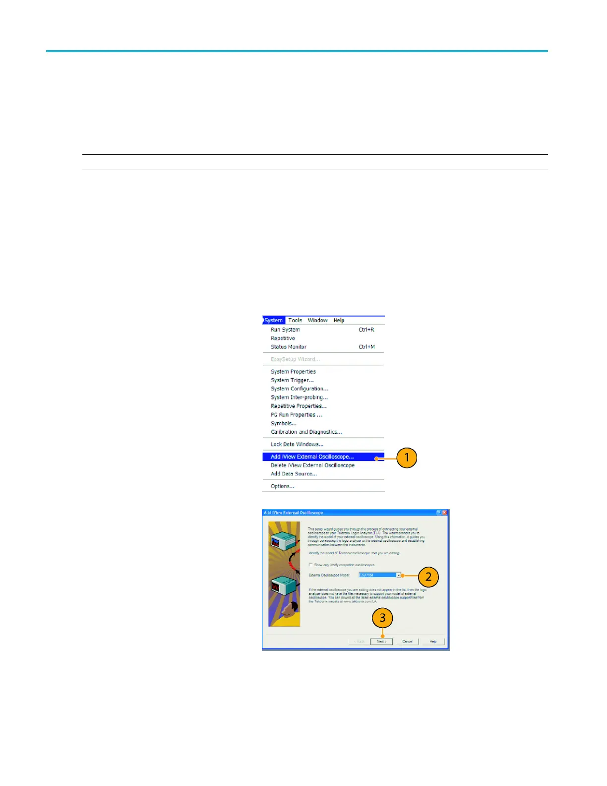
1. Select Add iView External
Oscilloscope from the logic analyzer
System menu.
2. Select your model of oscilloscope.
3. Follow the on-screen instructions, and
then click Next.
4. See your Tektronix Logic Analyzer
doc
umentation for more information on
correlating data between your Tektronix
oscilloscope and logic analyzer.
180 MSO4000B and DPO 4000B Series Oscilloscopes User Manual
 Loading...


