HDVG7 HDTV Digital Video Generator module
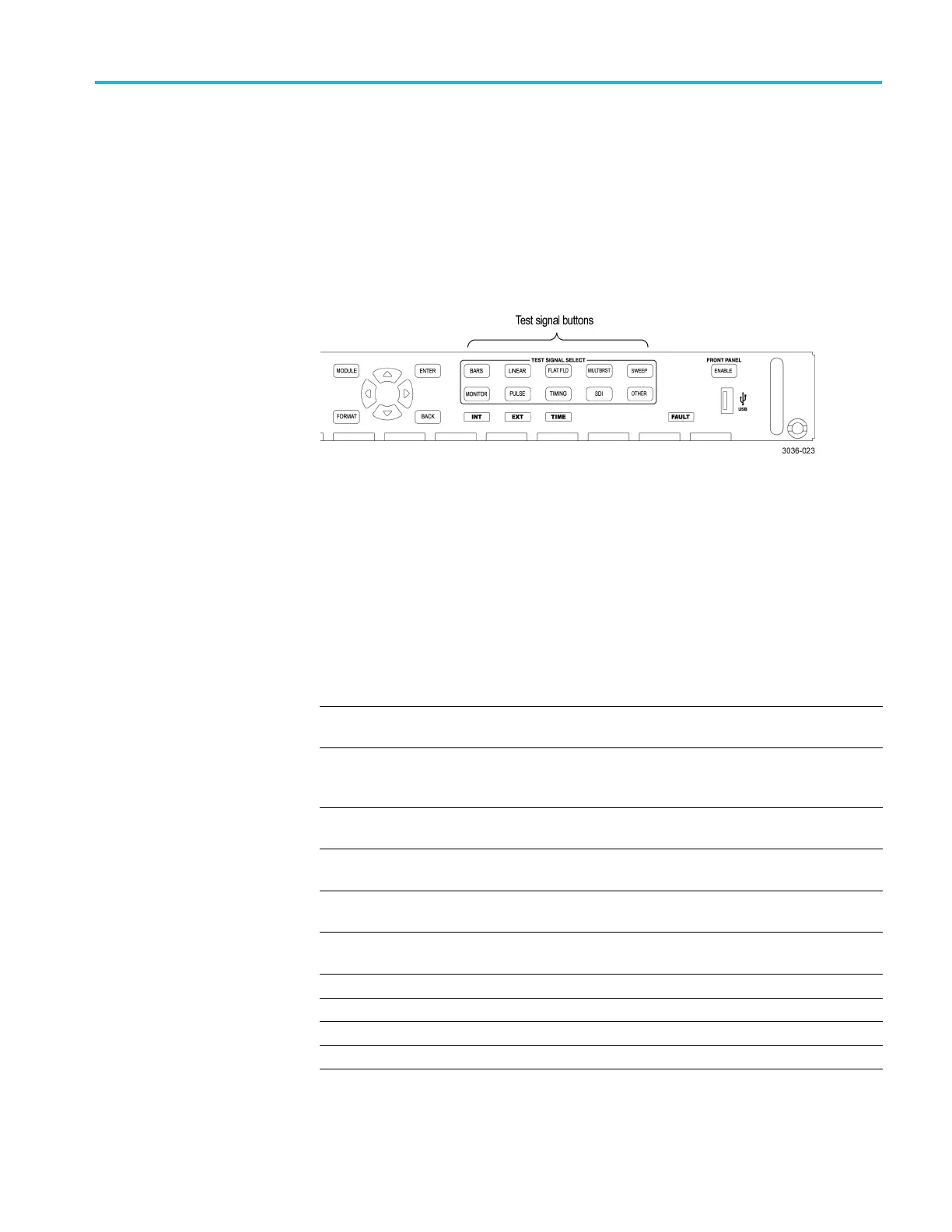
To select the te st signal
All of the signa
l sets that are available in the module are already assigned to the
corresponding test signal buttons. When the HDVG7 module is selected and you
press any of the front-panel test signal buttons, the selected signal in the signal set
is output. (See Figure 3-102.)
For example, when you press the COLOR BAR test signal button, a signal in
the Color Bars signal set is output. Use the left (◄)orright(►) arrow button, or
press the COLOR BAR test signal button repeatedly to select a different signal
from the Color Bars signal set.
Figure 3-102: Front-panel test signal buttons
You can download a frame picture file (created by the Frame Picture Generator)
to the mainframe and output the picture from the HDVG7 module. Refer to the
TG8000 PC Tool
s Technical Reference for detailed information on how to create,
download, and output a frame picture.
The following table lists the signal set assigned to each test signal button and
shows the test signals that are available in each signal set.
Table 3-45: HDVG7 module signal set assigned to the test signal buttons
Button name Signal set Signals in the signal set
COLOR BAR Color Bars 100% Color Bars, 75% Color Bars,
SMPTE Color Bars
LINEARITY L inearity
5StepStaircase,LimitRamp,Ramp,
Shallow Ramp Matrix, Shallow Ramp
Valid Ramp
FLAT FIELD Flat Fields
0% Flat Field, 50% Flat Field, 100%
Flat Field
MULTI BURST
Multiburst Multiburst 1-10 MHz, Multiburst
10-20 MHz, Multiburst 20-30 MHz
SWEEP Sweep 100% Sweep 1-15 MHz, 100% Sweep
1-30 MHz
MONITOR
Monitor
75% Blue Field, 75% Green Field, 75%
Red Field, Convergence
PULSE BAR Pulse & Bar
2T30 Pulse and Bar
TIMING
Timing
Bowtie 1ns Markers, Co-site Pulse
SDI SDI Test Equalizer Test, PLL Test, SDI Matrix
OTHER
—— ——
TG8000 Multiformat Test Signal Generator User Manual 3–231

 Loading...


