SDI7 Dual Channel SD/HD/3G SDI Video Generator module
To select the test sig n al on
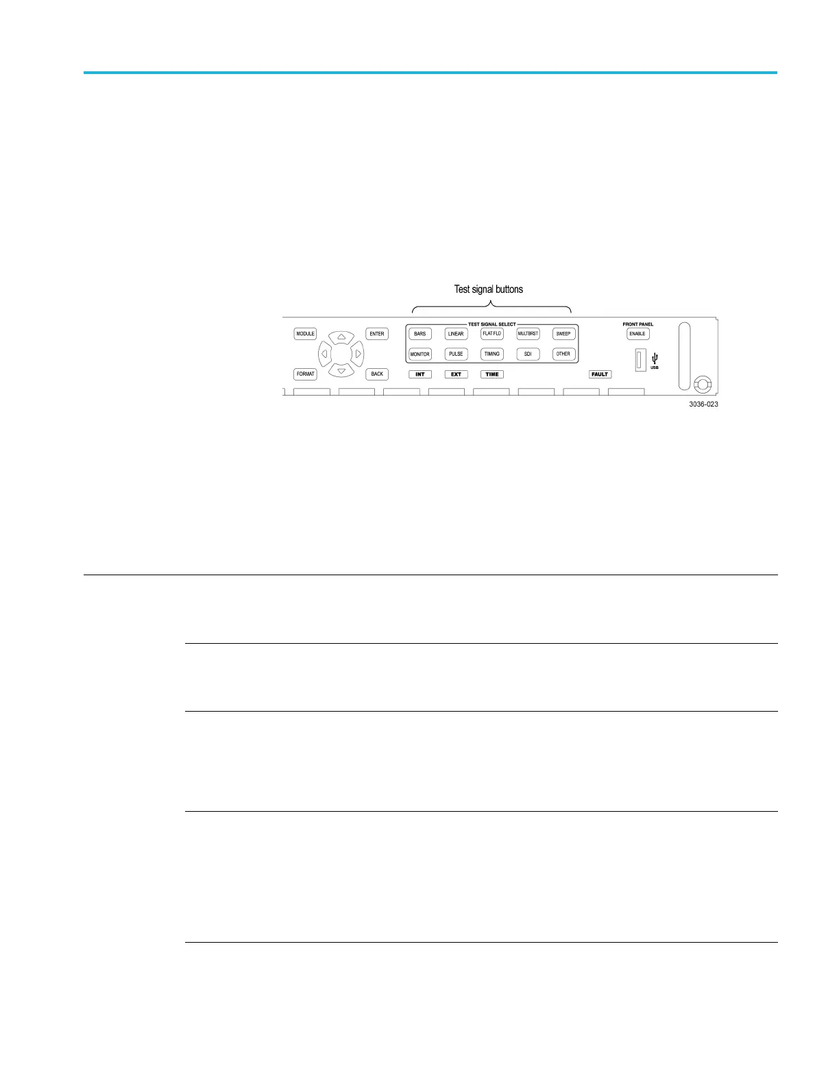
the SDI7 module
All of the signa
l sets that are available in the module are already assigned to the
corresponding test signal buttons. (See Table 3-59.) When the SDI7 module is
selected and you press any of the front-panel test signal buttons, t he selected
signal in the signal set is output. (See Figure 3-115.)
For example, when you press the COLOR BAR test signal button, a signal in
the Color Bars signal set is output. Use the left (◄)orright(►) arrow button, or
press the COLOR BAR test signal button repeatedly to select a different signal
from the Color Bars signal set.
Figure 3-115: Front-panel test signal buttons
The following table lists the signal set assigned to each test signal button and the
signals that can be selected in the s ignal set when the module is in generator mode.
Table 3-59: SDI7 module signal sets assigned to the test signal buttons
Button name Signals in the signal set Description
COLOR BAR 100% Color Bars,
75% Color Bars (100% White),
75% Color Bars (75% White)
Eight full-height bars of white, yellow, cyan, green, magenta, red,
blue, and black. This pattern is available with three variations, at
100% value for all bars, at 75% value for colors and 100% for
white, and at 75% value for all bars.
100% Color Bars Over Red,
75% Color Bars Over Red
These variations on color bars are available only i n the 625 50i
format of the SD output mode. They consist of the 75% or 100%
color bars signal on the top half of the raster, and a matching 75%
or 100% red field on the lower half.
SMPTE EG1 Color Bars Color bars per SMPTE EG 1-1990. This pattern includes 75%
color bars, reverse blue bars, −I and +Q sections, black, white,
and pluge sections. Note that this pattern is only available for
YCbCr formats, since the −I and +Q sections contain c olor
components outside of the legal RGB gamut. For the SD output
mode, this pattern is available only for the 525-line 59.94i format.
SMPTE RP219 Color Bars Color bars per SMPTE RP 219-2002. This pattern is intended for
16×9 aspect ratio displays, with additional elements as compared
to EG1 bars. The SDI7 implementation includes −I and +Q
sections, but unlike the similar sections in EG1 bars, they have
additional luminance to stay within R GB gamut. The −2% patch
of the pluge section is clipped to 0% black for XYZ formats. For
SD, the color bars are the 4:3 aspect ratio version, as if converted
from the 16:9 image with a center cut.
TG8000 Multiformat Test Signal Generator User Manual 3–261

 Loading...


