SDI7 Dual Channel SD/HD/3G SDI Video Generator module
Where AR = aspec
t ratio (1=16:9, 0=4:3), T = top bar d ata flag, B= bottom bar
data flag, L = left bar data flag, and R = right bar data flag.
Note that thes
e are all eight-bit values for the respective User Data Word. The
SDI7 module will automatically calculate the parity bits when Parity is set to
Automatic, which is the default.
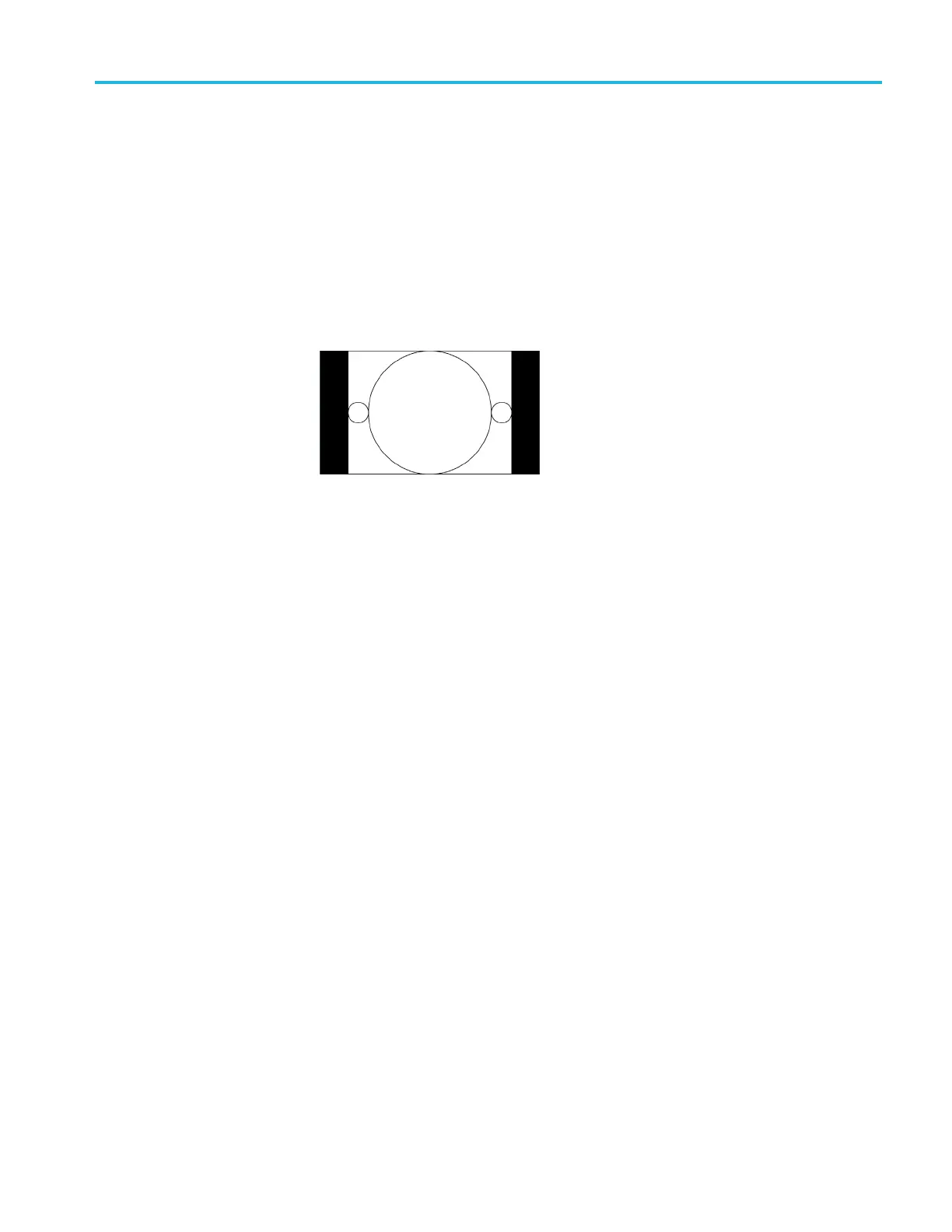
Most AFD codes do not require bar data information; only the first user data
wordneedstobedefi ned. For example, one common AFD code for a 16:9 coded
frame is “1001” (9), which indicates a 4:3 image, horizonta lly centered, with
pillarbox
es, as shown in the following figure:
Figure 3-140: AFD code “1001” for a 16:9 coded frame
Theref
ore, for this AFD code set the data words as follows:
UDW [000]:
UDW [001]:
UDW [0
02]:
UDW [003]:
UDW [004]:
UDW [0
05]:
UDW [006]:
UDW [007]:
0x4C
0x00
0x00
0x00
0x00
0x00
0x00
0x00
The AFD ancillary data packet should be located in the active line portion of
the
vertical ancillary space (VANC), but no earlier than the second line after
the RP 1 68 switch point. Line 9 with a sample offset of 0 (first word of active
video, immediately after SAV) is a suitable location. The selected video channel
should be “Luma” for most ancillary packets, including A FD. Finally, set the
ANC PAYLOAD Output mode to Continuous to start AFD insertion of the
active test signal. For this example, t he SMPTE RP 219 color bars are an effective
t
est p attern, because the center section of the 16:9 test signal contains the original
4:3 aspect ratio SMPTE pattern.
TG8000 Multiformat Test Signal Generator User Manual 3–331

 Loading...


