Getting started
Converter func
tion.
21. Set the HDTV video generator as indicated below:
Output signal: Ramp
Format: 1080 59.94i
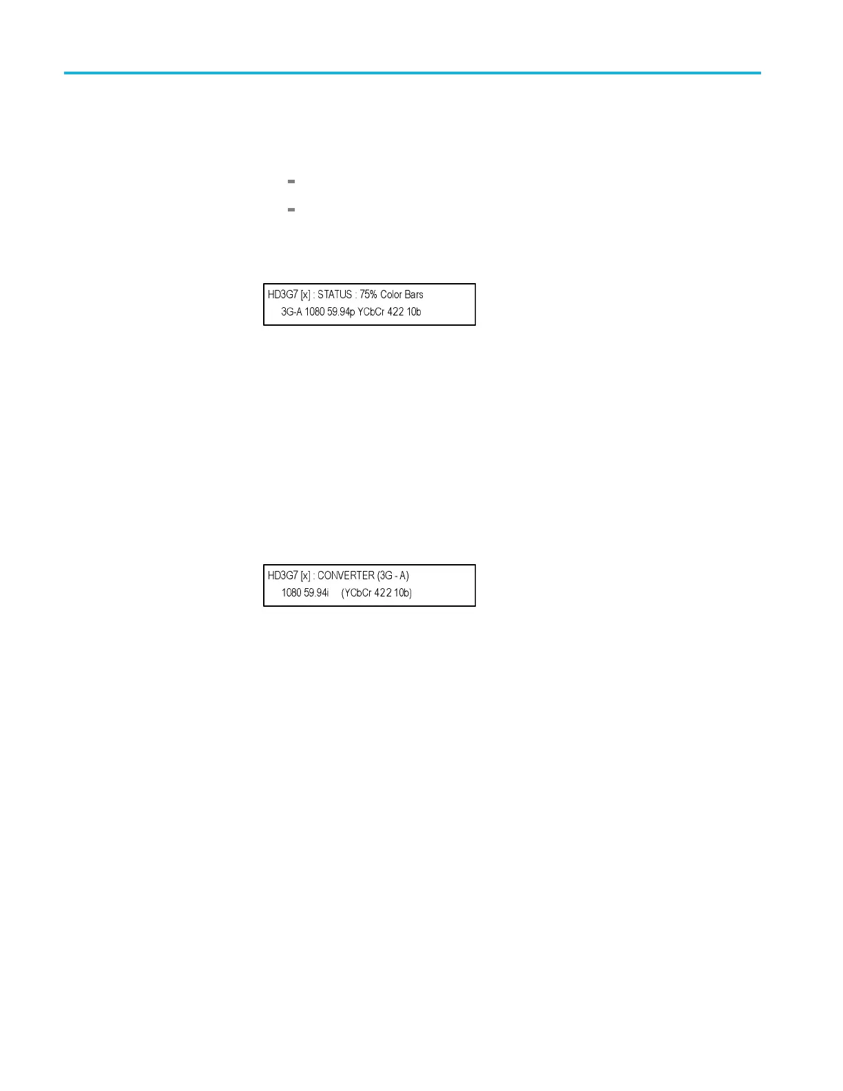
22. Press the front-panel MODULE button until the HD3G7 main menu shown
below appears .
23. Connect the output connector on the HDTV video generator to the HD SDI
IN connector on the HD3G7 using the 75 Ω BNC cable.
24. Connect the SIGNAL 1 output connector on the HD3G7 to an SDI input
connector on the waveform monitor using a 75 Ω BNC cable.
25. Press the FORMAT button and use the left (◄)orright(►) arrow button to
select 1080 59.94p, and then press the ENTER button.
26. Press the OTHER button to select the converter mode.
27. Press the BACK buttontoreturntotheSTATUS menu, which should now
look like the one below:
28. Check that the STATUS display shows 1080 59.54i as the input.
29. Press the up (▲) arrow button to d isplay the DIAGNOSTICS menu.
30. Press the ENTER button to access the DIAGNOSTICS menu, and then
use the left (◄)orright(►) arrow button (if necessary) to navigate t o the
DIAGNOSTICS : PLL STATUS page.
31. Check that the Jit reading shows Lock.
32. Press the right (►) arrow button to display the CR C Errors submenu and
monitor the CRC error counts for five seconds.
33. If there are CRC errors, press the right (►) arrow button until you see the
Clear CRC Errors menu, and then press the ENTER button to clear the
errors.
34. Press the right (►) arrow button to scroll through the menus and check that
the voltage readings show (OK).
35. Checkthata108059.94prampsignalis displayed on the waveform monitor.
1–38 TG8000 Multiformat Test Signal Generator User Manual

 Loading...


