3. Run the mains cable (for 230V AC, 50/60Hz) through opening 7, shown in Figure 11
and connect it to the mains terminal – Figure 12. Use one of the three plastic caps to x
the mains power cable in Clamp 10 (Figure 11). With the additional provided spare parts
kit use the two screws (tapping screw 2.9x13 cross slot DIN 798) to secure the cap to
the clamp.
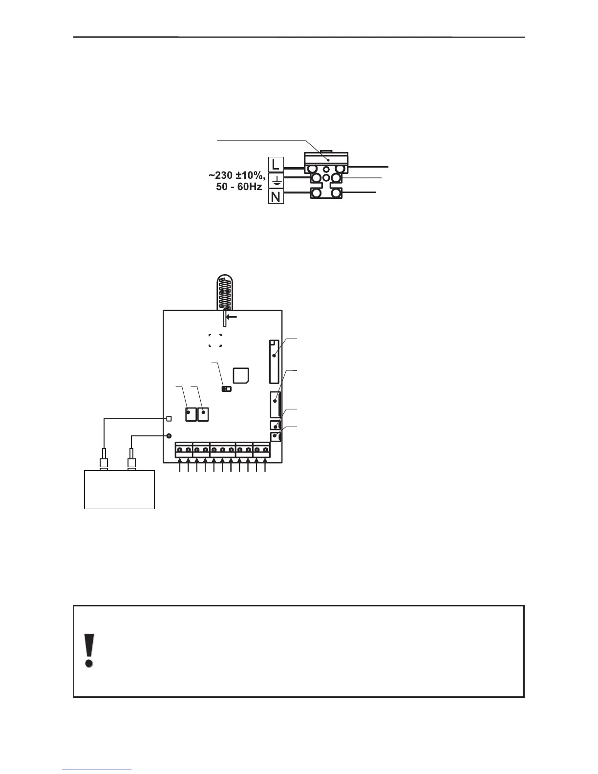
Figure 12. Connecting to the mains terminal.
4. Connect the ribbon cable to the display and the one of the built-in siren to the main
module see Figure 13.
Figure 13.
Overall view of the main module and description of the inputs and outputs.
5. Install the charge battery (12V DC, 1.2 ÷ 7 Ah; it is recommended to use a YUASA
#NP-12 model) designed to provide backup power supply in case of mains failure
(230V AC).
NOTE that the battery has to be connected to the AVA control module AFTER
the initial system start-up - see §2.3, page 15.
Observe the polarity of the battery terminals. Otherwise the self-recoverable
fuse BATT will turn out.
OBSERVE SAFETY MEASURES WHEN USING 220V!
AC
GND
Zn1
PGM4
PGM3
PGM2
PGM1
AUX
Zn2
ANTENNA
AT TENTION
DO NOT TOUCH
THE ANTENNA
:
!
1
2
3
4
5
6
7
-
-
-
-
-
-2А,
-±
,
~230 ±
±
-,
,
-
RESET Jumper
Flat terminal for connecting the keypad
Flat terminal for connecting the dialler
Connector for connecting the built-in siren
Connector for connecting the tamper-switch
Battery Fuse
type self-recoverable
AUX Output Fuse 1A,
-
VAC 10%, 50 60Hz
- 12V,
1A
-
-
type self-recoverable
Mains Power Supply
Power Supply
for detectors with consumption up to
Programmable output
with power transistor
Programmable outputs
with small-power transistor
Terminals for wire zones
Common ground
AC
AUX
PGM1
PGM2-PGM4
Zn1, Zn2
GND
BATT
±AUX
Cable shoes for connecting
the accumulator
+
-
1
2
3
4
5
-
+
6
7
black
red
Accumulator
battery
V, 1,2 7Ah12