2.3. Initial Start-up of the Control Panel
After the system is installed, it should be started-up: i.e. the power supply is turned on
(initial power supply) with a mounted jumper for full reset (located next to the processor
– see Figure 13, page 13).
Before performing a full system reset (to remove the jumper from the control module,
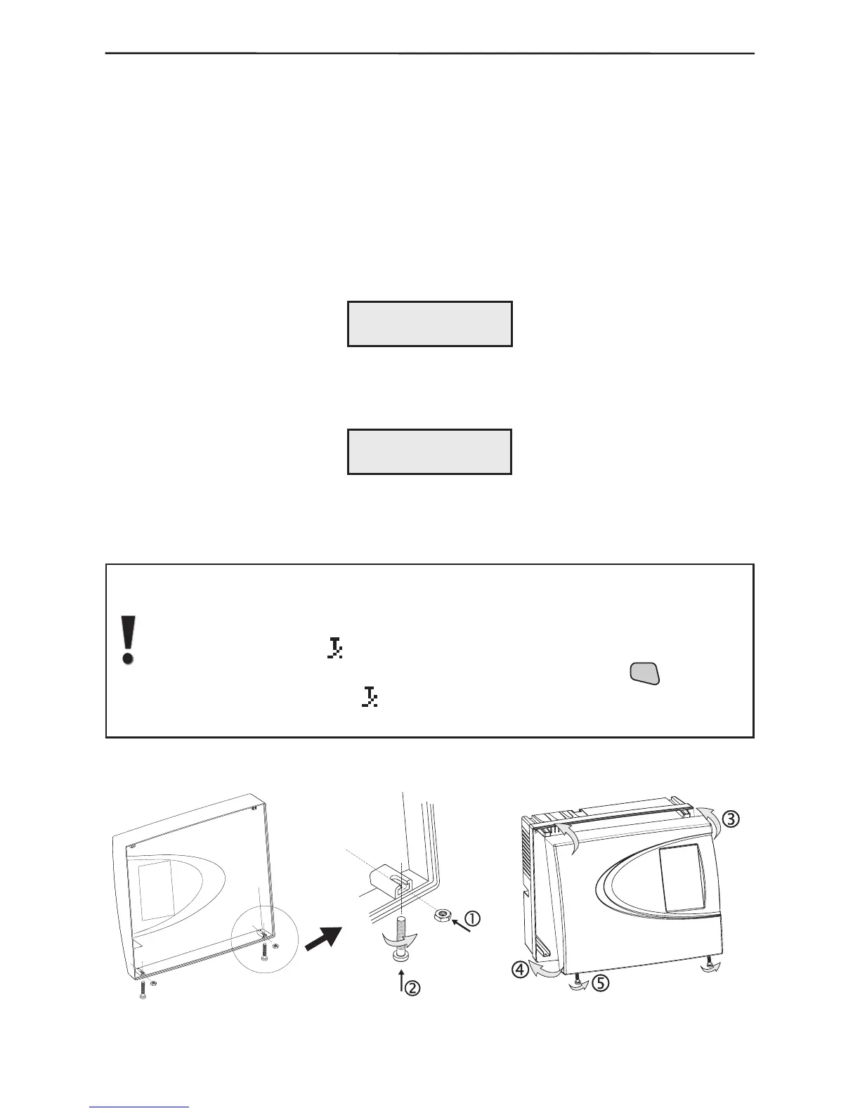
next to the processor), prepare the box to be closed by placing the nuts from the spare
parts kit in the holders on the internal side of the cover – Figure 16. Turn the two M3x16
screws into the cover openings so that they join the nuts but do not go all the way.
Turn on the main power supply with the mounted jumper for full reset of the control
module. The system will begin to operate and the display will indicate:
Remove the jumper and wait for several seconds for the system to restart. The display
will indicate:
Connect the battery terminals, observing the polarity.
Place the top cover and wind the screws to the end, as shown in Figure 17.
After performing a full system reset AVA system will automatically go on
normal working mode and a sound signalization for open tamper in the
system (the tamper of the control module) will turn on, and on the LCD will
start blinking symbol
.
The sound signal can be stopped by single-pressing the