2.2.2 Box Installation
1. Use the provided prole board (see
the back of the packaging) to drill mounting
openings (6 - 8 mm) at the installation
location - Figure 10.
For mounting onto a brick wall it is
recommended to use 4,2x35 DIN 7981
screws and 6x30 UN 9802 plugs.
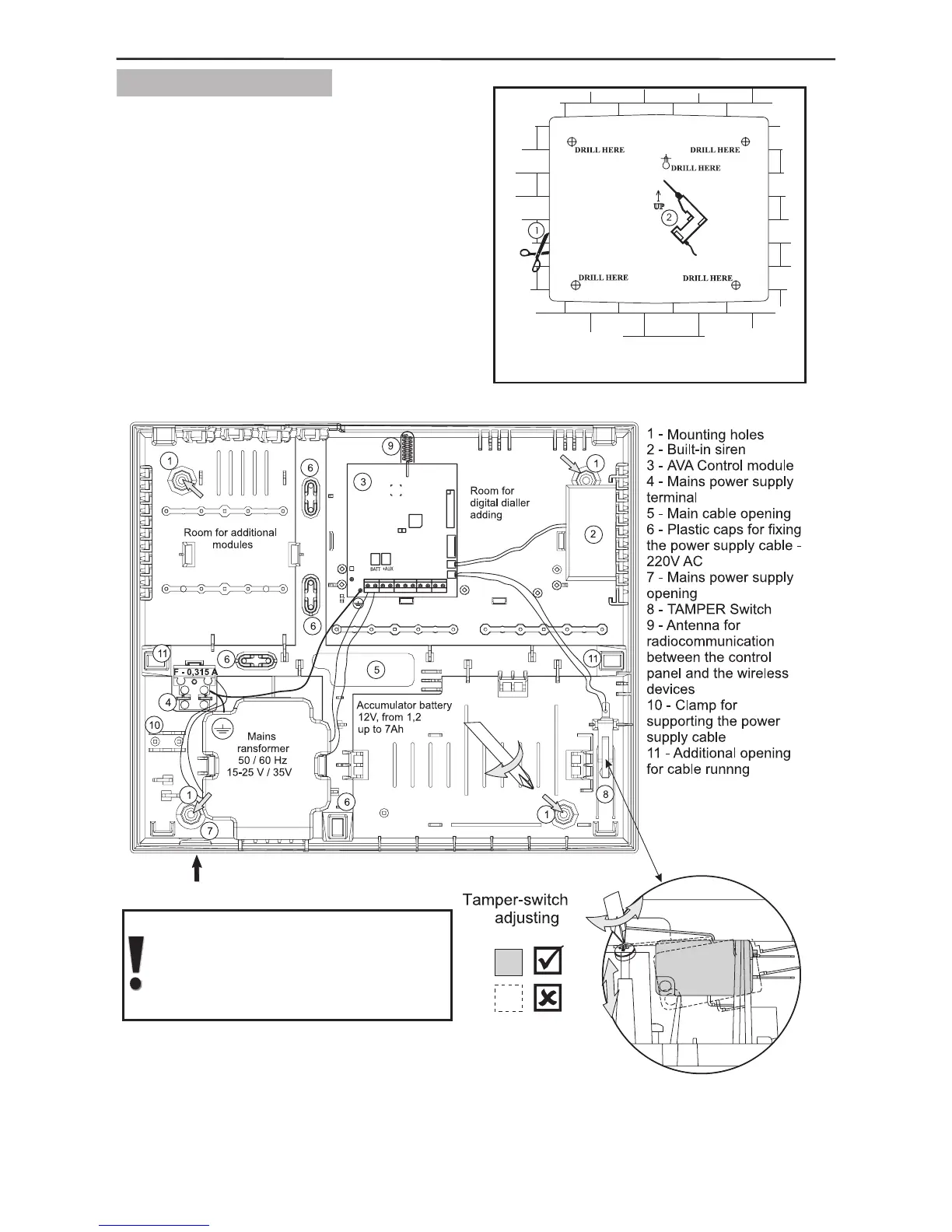
2. Install the back of the box on the wall
and adjust the tamper-switch as shown in
Figure 11.
Adjust the temper-switch with
the help of the screw below it so
as viewed from aside to be
horizontal.
Figure 11. Location of the modules in the box and the electrical
connections among them.