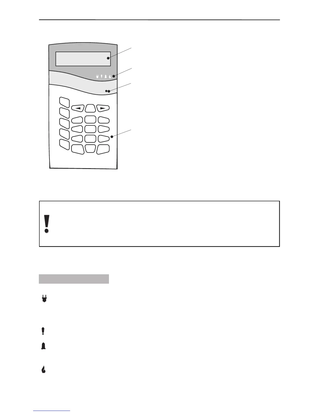
1.3 Control Panel Keyboard
The main panel keyboard consists
of an LCD Display, LED Indication
and 20 buttons with general
and special functions. A beep is
generated to acknowledge the
pressing of any button. A sound
signal is also used to indicate where
a specific operation is accepted or
rejected. The control panel sound
signals are explained in detail in
§1.3.5, page 8.
The user or engineer codes provide
access to the various alarm system
programming and control menus
unless where the Single-Touch
Buttons option has been activated.
The default value of the user menu code is 0000, and the engineer code is
7777. Any changes in both access codes is described in detail in §3.3 User
Programming, page 38. The access codes shall restore their initially preset
parameters only after complete nullication (full system reset) of system
parameters.
The programming and control menus and submenus have been numbered and are
located in a tree structure – see The Appendix: General Structure of System Menus.
1.3.1 LED Indication
There are four LEDs on the main panel keyboard which indicate:
220V (green) - lights up permanently to indicate mains power supply and turns
off when disrupted. The indication can be delayed in time via programing - §3.6.5
Programming Backlight Turnoff Time and Generating of an Event for Mains Power Lost,
page 45.
TROUBLE (red) - lights up to indicate an open tamper in the system; blinks to indicate
system trouble. When lit it is recommended to contact your installer.
ALARM (red) - lights up permanently to indicate an alarm event; blinks to indicate
entry and exit countdown time for encouraging relative actions for disarming or evacuating
the site.
FIRE (red) - indicates a re in the premises.