2.2.3 Connecting Wire Zones and Programmable Outputs
The system programmable outputs (PGMs)
are transistor type (NPN) with a 1K resistor
in the collector. By default all PGMs are in
NC state (normally closed contact) – i.e. the
programmable output is ON and the polarity of
the output is grounded. PGM1 is a power output,
whereas PGM-s 2, 3 and 4 are low current
outputs. The outputs are designed to be used
as open collectors: i.e. for switching over from
load to ground. The additional 1K resistor in the
collector serves as an additional output level in
case the output is potential. Then serviceability
shall be restricted by the resistor.
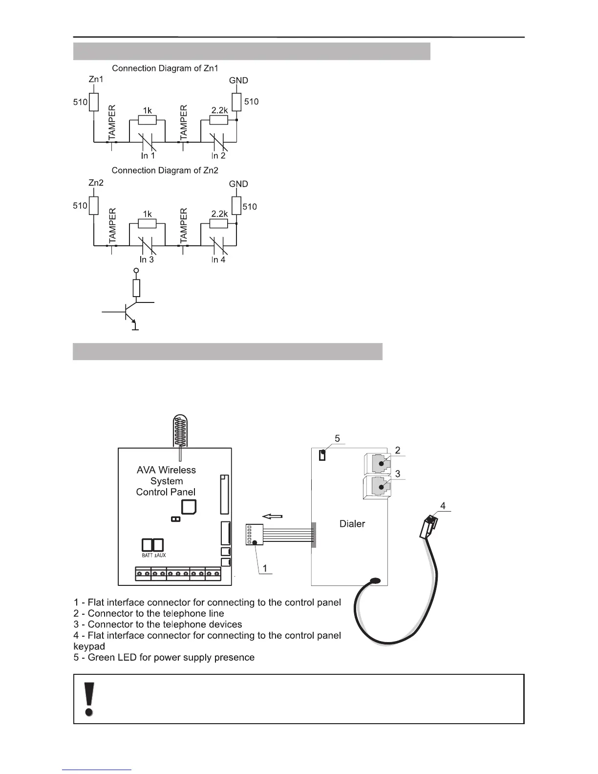
2.2.4 Connecting a Digital Communicator (Dialer)
Figure 15 shows how to connect the CPC 100 TE Digital Communicator board to the
control panel. If the connection is correct and power is supplied to the control panel a
green LED will begin to blink in the top left-hand corner of the communicator.
Connect the Dialer to the AVA control panel only when the main power
supply is switched off. The Dialer has to be the rst device connected to
the telephone line, in order to provide it with highest priority in operation.
Figure 15.
Dialer
connecting
Figure 14.
How to connect the wire zones and scheme of
a programmable output