Addressable Fire Panel IRIS - Installation and Programming Manual 15
After calculating, the maximal length of the cable is determined according:
· If L
C
≤ L
C2max
and L
C
≤ L
C3max
- the re pane will be able to communicate with the devices in the
loop and also will be able to identify the presence of double address.
· If L
C2max
< L
C
≤ L
C1max
and L
C
≤ L
C3max
- the re panel will be able to communicate with the devices
in the loop but will not be able to identify the presence of double addresses.
ATTENTION:
Always calculate the maximal cable length according the mentioned above formulas!
IF L
C
> L
C1max
or
L
C
> L
C3max
- the re panel would not be able to communicate with the devices.
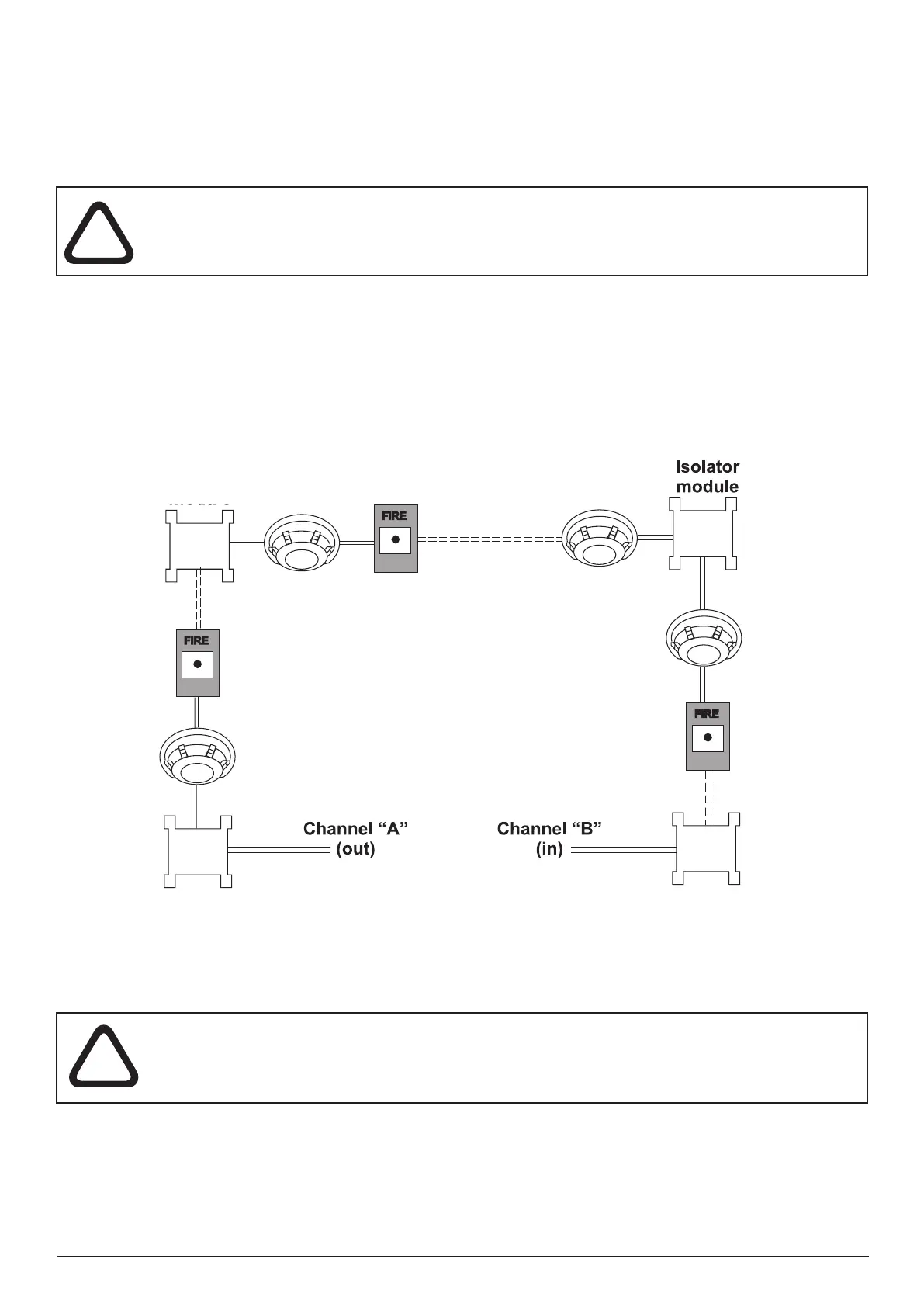
The connection diagram shown on Figure 16, gives the possibility to protect devices against opening and
short-circuit. For example, short-circuit in section 2 will not inuence the operation of sections 1 and 3. The
isolator modules at the both ends of section 2 will isolate it, and section 1 and 3 will continue working properly,
as section 1 will operate by supply from the channel “A” and section 3 - by supply from channel “B”. Since
the re panel will not be able to communicate with the devices from section 2, it will generate an alarm signal
for lost devices and open circuit.
Isolator
module
Section 1
Protected
premises
Isolator
module
Isolator
module
Section 3
Protected
premises
Section 3
Protected premises
Figure 16. Example for connecting of detectors and call points to a loop expander.
The maximum number of devices between two isolator modules is 30!