16 Addressable Fire Panel IRIS - Installation and Programming Manual
Red LED for
indication of V.220
Black
Black
Yellow-green
Black
Black
Yellow-green
Fuse
F-Type
2
А
Main
Power
Source
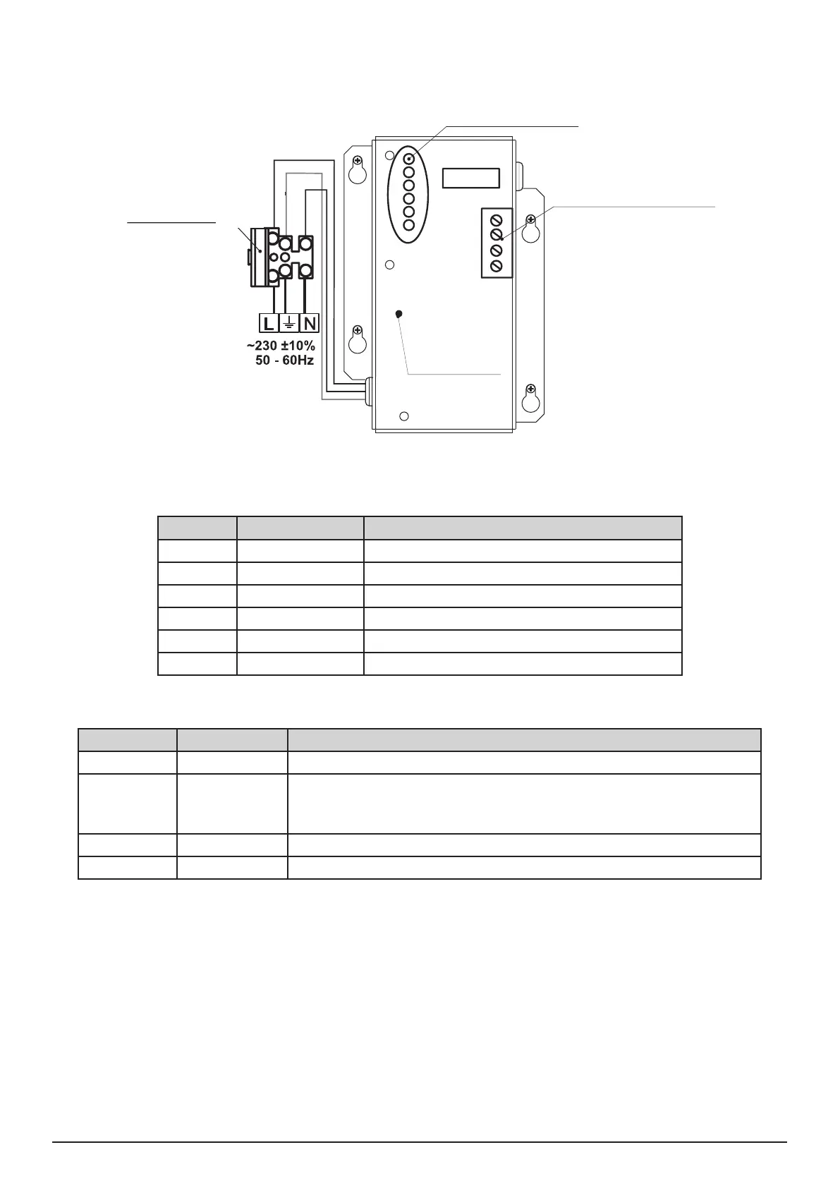
LED-indication for the status
of Main Power Source.
Terminal block for
external power supply.
1
2
3
4
5
6
1
2
3
4
Figure 17. General view of the power source and the terminal.
LED-indication of the power source
LED Function Description
1 AC LOSS Main power supply loss 220V.
2 Charger Fault Problem with the battery charging.
3 BATT LOSS Battery loss.
4 BATT Low Discharged battery.
5 EARTH FAULT Resistance to GND ≤ 10kΩ.
6 Rx / Tx Shows the communication with the panel.
Terminal Block for connecting to external power supply.
Terminal Function Description
1 GND Input for connecting of external power supply EARTH.
2 FAULT OUT Fault output, turns on when a problem with the main power supply
occurred. Connect it to the input (Fault In) of the external power
supply.
3 FAULT IN Input for connecting the Fault output of the external power supply.
4 +13.8V External power supply input.
Before the mains supply is switched on, check the correct connection of each loop, sounder or any
other input or output.
Black
Black
Red
LED indication for the status
of Main power source
Terminal block for
external power supply
Main
Power
Source
Fuse 2
AF type
Red LED for
220V indication
Black
Black
Yellow-green
Black
Black
Yellow-green