46 Addressable Fire Panel IRIS - Installation and Programming Manual
Disabled zone (red) - The zone is disabled
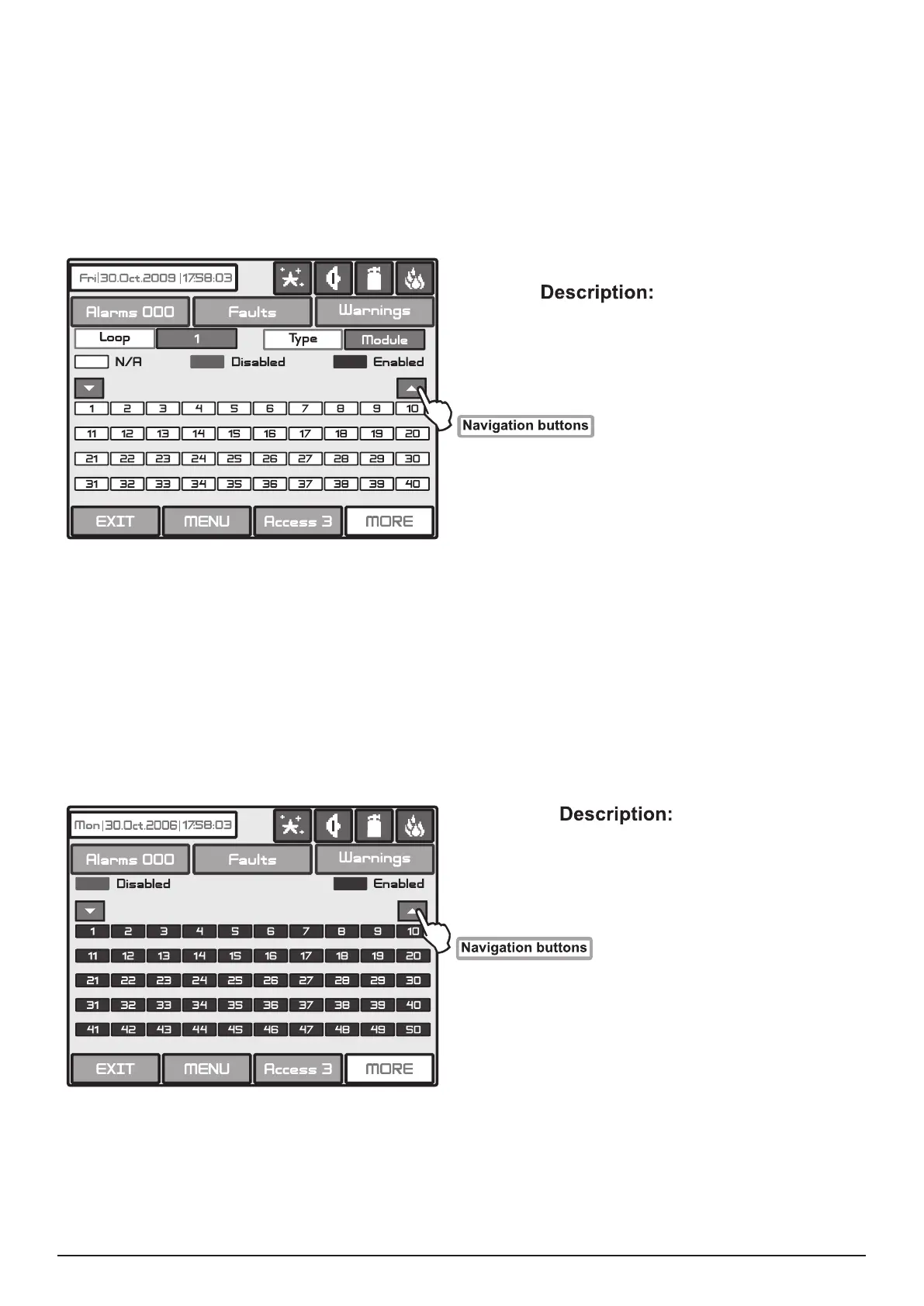
Enabled zone (green) - The zone is enabled
N/A (white with black digits) - There is no device at the address
Disabled (red) - The device is disabled
Enabled (green) - The device is enabled
The user/installer could rst look at the current status of the loop devices by choosing “View” button situated
next to the “Loop devices” button - see Fig. Screen 35. On the screen of the panel is displayed the current
status of the loop devices programmed earlier in the system (see part Programming, item 3.3.2 Loop De-
vices) - Fig. Screen 36.
In the case of a disabled device, the panel generates a “Loop Device Disabled” error message and the
“DISABLE” and “GENERAL FAULT” LEDs are activated. Any disabled device will not generate messages
to the panel. In the case of disabled devices associated with a given zone, where it has passed into Normal
mode, and of all devices without 1 if the zone is in “2Devices” mode, the same is automatically disabled and
a “Zone Disabled” error message is generated.
Fig. Screen 36
From the screen for the current status of the loop devices the user/installer can introduce new settings as
choose the button with the number of the respective device 1,2,3…250 (LOOP TTE) or 1 to 100 (LOOP SS).
With the buttons ▼▲ is possible to be viewed the all loop devices in the conguration of the system. By
choosing a button with a device number the user/installer moves to menu for setting of the parameters of the
respective device see Fig. Screen 8, part Programming.
The user/installer could rst look at the current status of the loop devices by choosing “View” button situated
next to the “Zones” button - see Fig. Screen 35. On the screen of the panel is displayed the current status
of the loop devices programmed earlier in the system (see part Programming, item 3.3 Zones) - Fig. Screen
37. In the case of a disabled zone, the panel generates a “Zone Disabled” error message and the “Disable”
and “General Fault” LEDs on the control panel are activated. Any disabled zone will not generate messages
to the panel.
Fig. Screen 37
From the screen for the current status of the zones the user/installer can introduce new settings as choose
the button with the number of zone 1,2,3…96 (LOOP TTE) or 1 to 100 (LOOP SS).. With the buttons ▼▲ is
possible to be viewed all zones in the conguration of the system. By choosing a button with a zone number
the user/installer moves to menu for setting of the parameters of the respective zone - see Fig. Screen 14,
part Programming. Note: From the disabling menu you can directly enter in the loop devices congu-
ration menu (Fig. Screen 8) /zone conguration menu (Fig. Screen 12) as choose “Loop Devices” /
“Zones” button (Fig. Screen 32).