Addressable Fire Panel IRIS - Installation and Programming Manual 31
3.4 Zones
Choose in sequence from the Main menu screen System - Programming - Zones.
The IRIS light addressable re panel avails of 96 zones. The FIRE and PREALARM conditions are indicated
by the help of the LED of the corresponding zone. In the PREALARM condition - the respective zone LED
blinks and a warning message is displayed on the screen. If there is a second activation of devices in the
same zone an alarm message FIRE is generated for the respective zone. To enter the submenu for zone
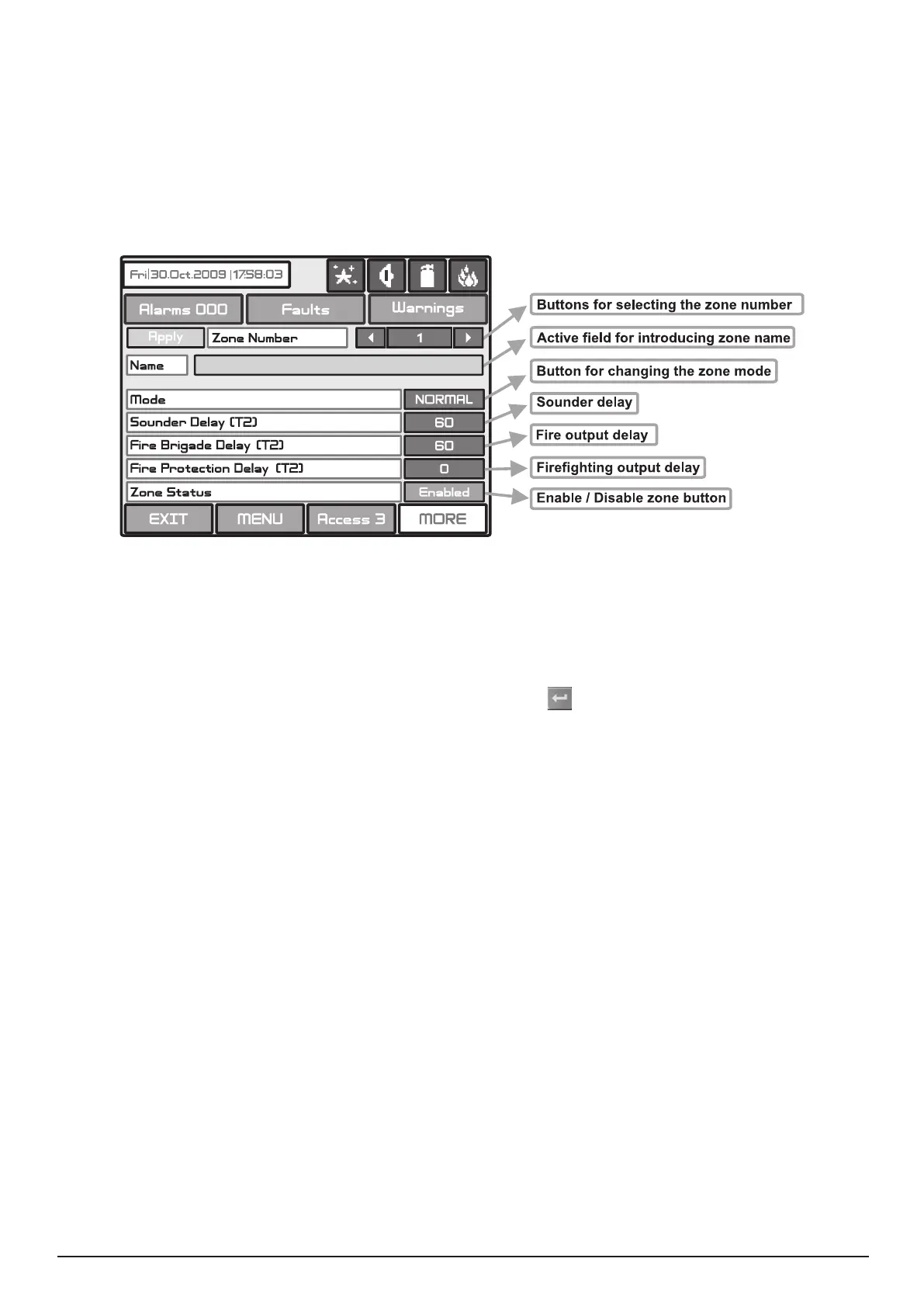
conguration, chose “Zones” button from Programming menu - Fig. Screen 3. The general view of the zone
conguration menu is shown on Fig. Screen 14.
Fig. Screen 14.
The zone number can be selected in sequence or directly, which can than be monitored.
Choose the button to enter the screen (Fig Screen 9), for introducing the zone name, which shall not exceed
40 digits together with the spaces. Verify the information with the
button.
Each zone has two working modes: NORMAL and 2DEVICES.
· In NORMAL mode any detector activation within the system generates an alarm event to the respective
zone.
· In 2DEVICES mode any detector activation within the system generates a PREALARM event to the respec-
tive zone, but also awaits the activation of another detector from the same zone to generate a FIRE signal.
The RESET command shall disable the FIRE and PREALARM events.
The delay can be within an interval of 0-540 sec.
In case of activation of more than one zone, the delays to the outputs are caused by the zone with shorter
delays.
The delay can be within an interval of 0-540 sec.
In case of activation of more than one zone, the delays to the outputs are caused by the zone with shorter
delays.
The delay can be within an interval of 0-540 sec.
In case of activation of more than one zone, the delays to the outputs are caused by the zone with shorter
delays.
Button for Enabling / Disabling zones.
All changed parameters are conrmed and saved by pressing the APPLY button in the upper left cor-
ner of the screen.
Т2 presents times for individual output delay setting. See APPENDIX E - Two steps of alarming algorithm.