32 Addressable Fire Panel IRIS - Installation and Programming Manual
3.5 Inputs
To enter the submenu for inputs conguration choose “Inputs” button from Programming menu – Fig. Screen
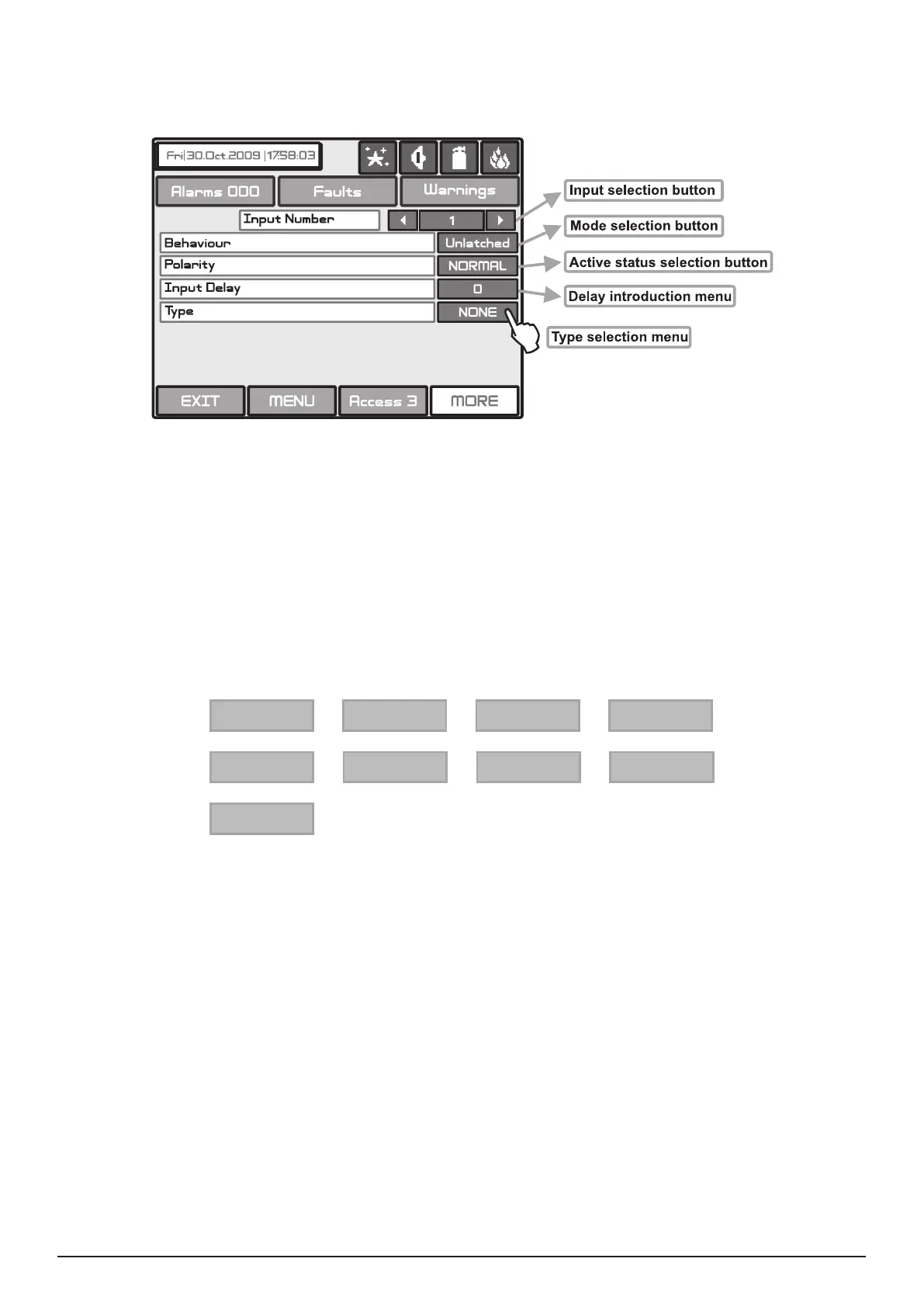
3. The general view of the menu for inputs conguration is shown on Fig. Screen 15.
Fig. Screen 15 – Menu for introducing input parameters.
. The delay can be within the interval 0–600 sec.
- the output is set at ON, when the result of the logical function is FALSE.
- the output is set at ON, when the result of the logical function is TRUE.
- deleted only after RESET.
- monitors the status.
By pressing the button for input type a new screen is displayed from which can be chosen the following types:
NONE Periphery
Loop
Zone
Time
Date
Action
General
Network
After choosing the desired type it is introduced in the Type eld of the screen - Fig. Screen 12.
Depending on the type of input after choosing the button MORE could be programmed the parameters of every input
type. The information is displayed on a separate screen.
There can be programmed the following parameters:
• PERIPHERY - Choose the MORE button. Set the parameters in the screen “INPUT Parameters - periphery devices”:
- Address of periphery device. Enter an address number from 1 to 10.
- Input of periphery device. The button have two states - ON and OFF, according the type of the device. Enter a
periphery device input number.
• LOOP - Choose the MORE button. Set the parameters in the screen “INPUT Parameters - loop devices”:
- Address of loop device. Enter an address number from 1 to 250.
- Loop number. Enter the loop number.
- Type of the device.
- Channel. Enter a serial number of an input accessible in the device.