Addressable Fire Panel IRIS - Installation and Programming Manual 13
The IRIS re panel operates with two loop controllers: Loop SS (System Sensor communication protocol) and
Loop TTE (Teletek Electronics communication protocol).
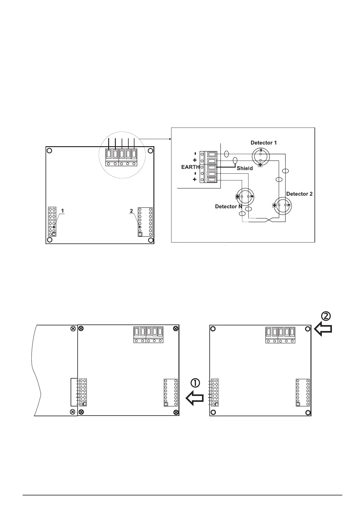
The Loop Controller (Figure 14) realizes the connection between the I/O Module and devices connected to
the communication line. The Loop Expander has two basic functions: 1. Gathers data from the devices in
the communication line and transfers it to the I/O Module; 2. Receives commands from the I/O Module and
transfers them to the devices connected in the communication line.
Every Loop SS provides up to 99 detectors and 99 modules.
Every Loop TTE provides up to 250 devices (detectors and modules, regardless of the type)..
The maximum current consumption of the devices in the communication line is I
max
= 500mA. If the consump-
tion exceeds this value an over-load protection would be turned on.
In the conguration of analogue-addressable re panel IRIS could be mounted up to 4 loop controllers.
1 - Interface connector for connecting the Loop expander to the I/O Module.
2 - Interface connector for connecting second loop expander.
Figure 14. General view of Loop Expander and an example for connecting devices to it.
First
Loop Expander
I/O Module
Second
Loop Expander
1 - Connect the interface connectors of the rst and the second loop expanders.
2 - Fix the second loop expander with supplied bolts in the kit to the metal box of the re panel.
!
Figure 15. Connecting of a second loop expander in the re panel conguration.
The method of adding third and forth loop expander is analogical to that shown on Fig. 15.
Loop Controller
I/O Module
First
Loop Expander
Second
Loop Expander