Addressable Fire Panel IRIS - Installation and Programming Manual 23
3.3 Devices
The addressable re panel IRIS light supports periphery and loop devices.
All “functional modules” connected to the control panel conguration are dened as Periphery Devices, and
have special programming and setting. The Main board is not a periphery device. All addressable devices
connected to loop expaneder are dened as Loop Devices.
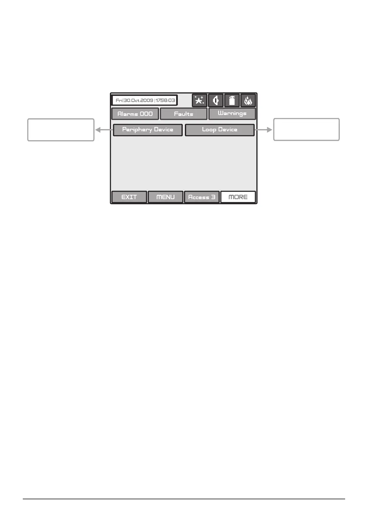
With choosing the “Device” button the user/installer enters a menu for choosing the type of the device - Fig.
Screen 4.
Fig. Screen 4.
Choosing “Periphery Device” button leads to submenu for entering the parameters of the available periphery
devices in the system conguration - Fig. Screen 5. The list of supported periphery devices is:
· PSU Power source - see Figure 5
· OUT (Input/Output Module) - 4 input/ 4 monitored outputs/ 4 relays
· OUT (Input/Output Module + 4 Relay Expander Module)
· LOOP (Loop controller type Loop SS and Loop TTE)
If there is no device detected on the current address, the address is
3.3.1.1 Physical Address of Periphery Device
The panel is able to operate with up to 10 periphery devices, addressed 1 to 10. The devices can be self-
addressed, whereby the rst along the loop acquires the lowest address. The power supply source always
acquires address 1.
You can choose the next/previous device address by pressing the
◄ ► navigation buttons.
3.3.1.2 Current Status of the Device
The running status of the device can be:
• NEW - the device is new to the system. It must be saved.
The main board is recognized a physical presence
of a device, which is not included in the system conguration. The new device has to be added to the system
conguration so the panel to be able to communicate with it - to receive an alarm or trouble messages, to
activate and to receive signals, etc. The new device can be add to the system conguration with pressing the
SAVE button.
1. A device has been physically added to the hardware conguration of the panel. Use the “SAVE” button.
(For example when a loop expander is added to the system conguration).
2. A device has been removed from the system conguration (with “REMOVE” button), but it is still present in
the hardware conguration - it is not physically removed. The panel will recognize the presence of the device
in the loop, but it is not added to the system conguration, so the device is NEW for the panel.
•NORMAL - the device is properly operating.
• FAULT - the device does not respond.
• TYPE ERROR - a device, different from that saved, has been detected. Use the “CHANGE“ button to
change the device type.
Button for entering
periphery devices pro-
gramming submenu
Button for entering
loop devices program-
ming submenu