18 Addressable Fire Panel IRIS - Installation and Programming Manual
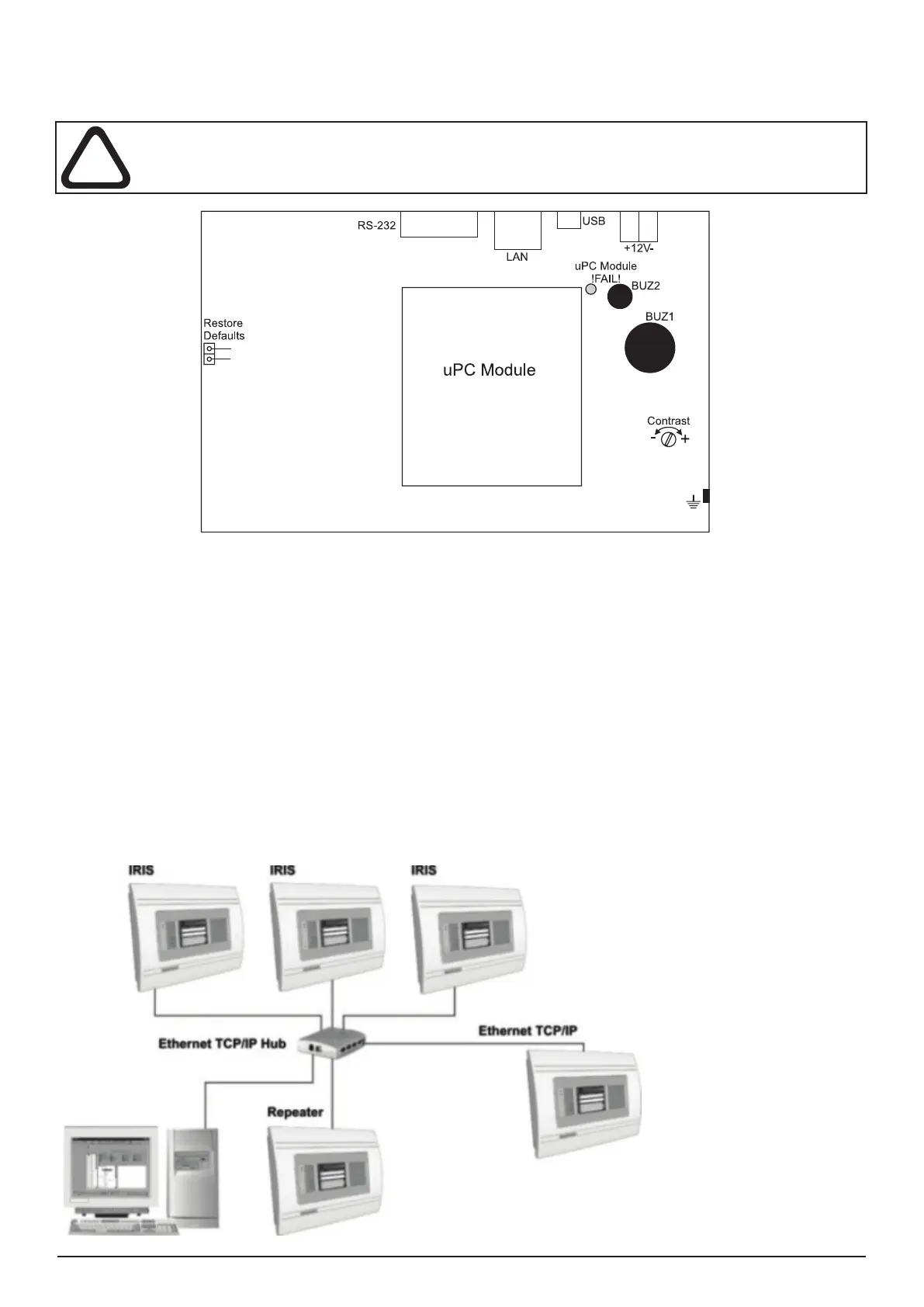
2.3 Main Board Schematics
The main board is situated on the back side of the front cover. On the main board is factory integrated a control module
- uPC Module, for control of the panel functions and operations.
ATTENTION: Adjustment on the main board can be done from an authorized personnel only!
Figure 19. Main Board with integrated Control Module.
Main board elements:
• Restore Defaults - Resetting the panels with default parameters.
• RS-232 - Serial interface
• LAN - Connecting to Ethernet network.
• USB - Mini USB connector.
• ±12V - Additional power supply.
• uPC Module !FAIL! - Yellow LED for uPC failure.
• uPC Module - Control module integrated to the Main board
• BUZ1/2 - Buzzers for sound signalization.
• Contrast - Adjusting the display contrast.
2.4 Network connection diagram
It is possible to connect some individual IRIS re panels in a network by means of a HUB and TCP/IP protocol - Figure
20. A supervisor PC, which could follow the current status of the individual re panels, monitors the current panel state.
Figure 20.